Quantcast
Channel: Ross Lillistone Wooden Boats
Viewing all 78 articles
Browse latest View live

New Website - Currently on the steep side of the learning curve

$
0
0
For those of you who may have subscribed to the new website, I have an uncomfortable feeling that you may have been deluged with "New Posts" as I have been progressing with the process of learning the new software characteristics.  If so, please accept my sincere apologies.

The good news is that I'm reading and experimenting diligently, and progress is starting to take place. I hope to get the 'Designs' section and the embryo 'Shop' looking more professional in a few days.

Concurrently, I'm working on the construction of a new mast for a customer, and it promises to be a major step forward in 'home-workshop-buildable' masts and other spars, without the need to cut 'Bird's Mouth' profiles. Many people don't understand that very small errors in the setting-up of the saw or router for 'Bird's Mouth' staves can have a huge effect on the diameter of the finished spar. Also, unless you have a very well arranged table-saw or router table, the potential for disaster is substantial...

They say that, '..pride comes before you end up with mud on your face...', but I'm quietly confident that the prototype mast I'm making will be faster, safer, and easier to build, and will have one REALLY substantial advantage over a 'Bird's Mouth' spar in that the wall thickness as a percentage of spar diameter will remain constant over the length of the mast. In the case of a 'Bird's Mouth' mast, the wall thickness (in percentage terms) increases as the mast tapers towards the tip - so much so that many masts become effectively solid towards the tip - not what is wanted at all! We need to keep masts light - especially as we go higher.

More to come when I get through this website business.

I've got a number of boats under construction or repair, but design will dominate before too long.

Ross Lillistone Website Coordination Test - Disregard

$
0
0
Ross Lillistone Website Coordination Test- Disregard

Website and Blog - Making Progress Slowly but with Determination!

$
0
0
Those of you who have been patient enough to be checking back to see how progress is going on the new website and the blog deserve an explanation about what is happening.

Due to an excess of work and looming deadlines, I've been caught between devoting time to the workshop and to development of the new website and the blog. Jobs in the workshop are well in hand (and must take priority), but by September my contracted work will be complete, and I'll then be turning my attention to fun jobs in the workshop, and lots more writing and design work. With good luck and sensible management, this should result in lots more articles and the publication of a stack of designs I have sitting in the wings waiting for finishing touches. Yes, I know you may have heard me say such things before, but I really am ploughing through the work at the moment, and I have for many months now had a moratorium on taking on any new building/repair work.

Tomorrow I'll post some photos of recent work, and a list of current jobs. One particularly interesting project is the building of a sixteen-sided mast for a large sailing dinghy. This mast is unusual in that it is not only hollow, but the wall thickness tapers as the mast tapers, so the wall-thickness as a percentage of mast diameter remains constant. Another interesting feature of this mast is that it incorporates an 'in-mast' hinge - sort of like a tabernacle without a tabernacle (see Woodenboat Magazine #237 for the idea)

Here is a slice off a test section of my mast construction method. There is a very good reason for the angle being cut into one side of each stave, rather than half the angle being taken of each side as they used to do it in the old days. Maybe I tell you why some day...
The sixteen-sided method is probably too labour-intensive to be practical without a production set-up, but the experiment has provided me with valuable insights, and has been R&D time well spent. Maybe eight-sided next time? The method does have advantages over the Bird's Mouth method, mainly in providing the ability to taper wall thickness as well as diameter - all in a home workshop.

I'm just beginning to come to grips with some of the complexities of the website program and associated plug-ins, so there will be gradual (but accelerating) addition of content and pages. Further down the track will come video tutorials on some interesting stuff.

Facebook and Twitter have me somewhat stumped at the moment, but that will improve with time - especially after workshop commitments are complete.

Micro Repair

$
0
0
Phil Bolger's Micro design is a favourite of mine, and of many other people around the world.

To the uninitiated, the boat looks somewhat like , well..., a box. The hull cross-section is, in fact, perfectly rectangular - something which leads many observers to underate the design and write it off as a crude and simple piece of work.

Well, Micro is a very simple boat to build, but only a genius - someone like Phil Bolger or Naval Architect C. Raymond Hunt - could design such a hull and make it work well (Phil Bolger was heavily influenced by C. Raymond Hunt, among others). It takes understanding to get the best from Micro and her free-standing cat-yawl rig, but if treated properly, she is an exceptionally good performer, while at the same time being cheap and quick to build, self-righting and self-bailing, roomy, and comfortable - all in a 15-1/2' x 6' x 18" package.

Cricket - a Micro which I built back in late 2001/early 2002.
In this photo you can see some of Micro's unusual features - flat bottom, extreme rocker, and rectangular sections. Very few people could design such a boat and make her a success. Very few people understand why the hull and rig work so well.
I'm not going to go into detail about the design aspects of the boat, but I will say that on one occasion I sailed her against a well-handled Navigator and an equally well-handled Penobscott 14, and even though I had two passengers, we beat both boats to windward, and pointed just as well. Now, the conditions were ideal for Micro, in that we were on a lake with about 10 knots of breeze and almost flat water, but her performance was superb, surprising me as much as anybody. It might have been different in a steep chop....

This particular Micro has been back to my various workshops on a number of occasions in order to have cockpit modifications made, and to have repairs carried out. Most recently, she came back to me after having been in collision (head-on) with a concrete floating walkway/wharf beside a boat ramp.

The damage was fairly localised around the bow transom and forward topsides, but Micro has a wonderful self-draining well, right between the bow transom and the forward bulkhead of the cabin, with a strong set of floorboards filling the space between the bow and the cabin bulkhead. The floorboards are at approximately the level of the painted boot-top (i.e. the division between the green and cream just above the waterline in the photo below).

My youngest boy, Steven, standing in the forward well back in 2002. He is standing on the forward well floorboards.
When Cricket hit the concrete walkway, the point of impact was head-on, almost exactly at the level of the floorboards. This not only damaged the bow transom, but also forced the floorboard panel back through the forward cabin bulkhead with great force. Micro is not a particularly light boat, carrying 195kg/412lbs of cast lead in her keel, weighing-in at around 500kg/1/2 a ton - so the damage was substantial.

Winch post pad covers most of the external damage. The paint is the original Hempel Polybest two-pack polyurethane which I applied in 2002! Notice how the plywood of the topside panels has de-laminated and split away from the bow transom framing. The damage is much worse than it appears.

Photograph of the inside of the forward well, looking towards the bow transom. The two large holes in the transom are the steps of the boarding ladder! (there is a hydrodynamic reason for the transom at the bow, but that is another story). You can see how the bow transom has been driven backwards through the topside panels, and that the framing has suffered serious structural trauma. In addition the planking-to bow transom epoxy fillets have been more or less destroyed.

Looking aft at part of the damage inflicted to the forward cabin bulkhead by the floorboard assembly. The boxed opening at the far left of the photo is the cabin ventilation opening - lets air through but keeps water out...

External damage to the starboard side of the bulkhead after initial paint removal...

......and the same on the port side. Doesn't look too bad, but represents serious structural damage on close inspection from inside and out.

Micro has a primary structure made from 6mm/1/4" marine plywood for the most part, with a substantial amount of 3/4" framing timber throughout in various widths. The boat relies on her large volume and surface area for her structural strength, and is well designed from an engineering perspective. However, like many aircraft, she is structurally strong, but vulnerable to point impacts.


Bulkhead damage

Damage to the bow

Damage to the bow.
The point of this post is to let people know that with careful planning and execution, a wood/epoxy boat can almost always be repaired to as good a standard (or better) as when she was built. Do not skimp on the process and avoid any temptation to "plaster over the cracks" so to speak - attention to structural detail is essential.

I may write more about the repair process use on this boat in a later post (no promises), but here are a couple of photos of the structurally complete repair, with only a few remaining paint details to be finished.


Just some painting to be done over the white two-pack epoxy primer/undercoat visible at the forward end of the keel, and some black boot-topping to be painted as well.
The repair process involved a lot of debris removal, fabrication of simple jigs to regain the correct hull shape, re-lamination of damaged plywood sheeting, plenty of epoxy, epoxy fillets, and glass fabric reinforcements - but the boat is alive and well!

The moral of the story is to build your boat properly in the first place, and repair her with care if the need arises. Have an open mind and be prepared to be inovative and to improvise. There is no reason why a home-built plywood boat should not last several lifetimes, even if damaged along the way. In fact, if you are not under too much time pressure, the process can be both challenging and rewarding.

Image Galleries on Website

$
0
0
After a lot of time spent learning about the intricacies of the dashboard on the new website, I have now been able to expand the list of picture galleries, and I have some images on every gallery.

This is very time consuming due to my ignorance when it come to working with Wordpress, but I have made significant learning progress over the last couple of days, and the site content will continue to grow.

The next thing I'll be doing is getting captions onto the gallery images, but it will be a gradual process over a week or so. Also coming in the near future will be extra pages in the 'Designs' section.

Several Videos added to bottom of Website Footer

$
0
0
I've added several videos to the bottom of the listing on the video page of my website - see video link on the footer of the home page.

More Detail on the Micro Repair

$
0
0
My recent post http://rosslillistonewoodenboat.blogspot.com.au/2015/04/micro-repair.html about repairs to a Phil Bolger Micro generated quite a bit of interest, and the following comment from Dave is an example:-

Thanks for the blog post, Ross, but you left out the details on the very parts I'd be most interested in seeing!

So if you do a future post on the nitty gritty details of truing up and patching the damage, I'd be most interested in that. 


Well, after taking initial photos of the damage, I didn’t many more during the repair process, simply because of time pressure – but here is a brief look at some aspects of the job: -


Initial job was to do a rough paint removal around all of the damaged areas to get a clearer idea of the extent of the damage, and to remove components/timber which had been destroyed. It also allowed ventilation and thorough drying.

A small puncture wound on the forward/starboard topsides on the outside, and

....the corresponding spot on the inside

Brutal removal of paint, damaged timber, and broken epoxy fillets 

Brutal removal of paint, damaged timber, and broken epoxy fillets

Paint removal from around the forward bulkhead on the interior of the cabin, where the floorboards had punched through.
Most of the work shown above was done using a heat-gun and a variety of sharp scrapers. The paint was all two-part epoxy primer/undercoat and two-part polyurethane topcoat (I know, because I built this particular boat myself fourteen years ago!) and removal was not ever going to be easy. However, the heat-gun and scraper combination is a good choice as long as you are very careful about never overheating the material and damaging epoxy adhesive and paint in locations which are not part of the repair. Other primary tools include chisels, 4" angle grinders, drills, sandpaper - and elbow grease!

Next stage was to carry out a more gentle sanding  using (in this case) a 5" random orbit sander, going down through the grits to about 120 or 180. On the internal areas, the job is more difficult to achieve, and I made heavy use of a Fein Multi-master detail sander and plain, simple sandpaper on a sanding block, or folded triple. Hard work!
See above comments

See above comments
I don't have many photos of the next stage, but it mainly involved pulling usable components back into position using a variety of improvised tools such as lengths of purpose-cut steel angle-iron with holes drilled at strategic locations, and also temporary through-bolts and backing pads. This work can be very satisfying if done properly, and with attention to detail. The key is to have an open mind, and to be prepared to be bold with your surgery.

Once I was happy that my bracing would all work, and that all interfering debris was removed from joints, I opened the whole lot up again, and even spread damaged components further apart (using wedges and chisels etc). With the components held apart, it was relatively easy to treat all surfaces with un-thickened epoxy resin and hardener in order to prime the mating and damaged joints using disposable bristle brushes. This is a very important step if you expect to achieve a good structural repair. With the work area well primed, it was then a matter of applying a rich mix of epoxy/hardener combined with the recommended structural glue/filleting powder additive.

With the structural epoxy  mix worked into all joining areas, I screwed, bolted, or clamped the repaired sections together, which is why the previous work dry-fitting the bracing and jigging was such an important step. Where appropriate, I applied structural epoxy fillets at the same time.


The above two photos show steel angle braces screwed into position over the epoxied repair. In the case of Micro I had the luxury of using straight sections of steel to hold things in place, but on more conventionally shaped boats the same thing can be done using shaped and bent timber splints. I'll show an example of this in an up-coming post on a Whitehall repair.
Interior shot of the repaired bow transom, topside planking, and forward bottom planking. This was taken while the initial epoxy work was still wet and ugly. This work was followed by additional cosmetic epoxy filling.
Exterior shot of the starboard, forward topsides repair taking place. The actual puncture damage is quite a small spot underneath the centre of the plywood pad.
Matching plywood pad on the inner surface of the topside panel. As you can see from the exterior shot above this one, I placed twelve screws through the hull and into the internal plywood pad and pulled them in tightly over the epoxied repair. Note that both pads have been covered in a film of plastic to prevent them being glued to the hull permanently. All of those screw holes had to be repaired later, but the repair turned out well. The plywood pads were large enough to take up the curve of the topside planking when screwed together.
Structural work complete, glass applied where required, fill and cosmetic work done, and the two-part epoxy primer/undercoat applied (the white paint - three or four coats)
Topcoat (two-part polyurethane) applied, with just some minor black line work to be done between the green topsides paint and the off-white bottom paint (that is my little step ladder relected in the paint by the way).
Because of a lack of photos, time and space, this has been a very brief overview of the job, but it may give you some inspiration. Unfortunately, I have no photos of the way I repaired the forward watertight bulkhead of the cabin - a job involving more steel angle bracing and numbers of temporary through-bolts, nuts and fender washers.  In a post in the not too distant future, I'll show the repair of a glued-lapstrake Whitehall tender which suffered very serious damage to her hull in an accident. Most people considered her a write-off, but we were able to give her a new life.

Just a word about repairing screw and bolt holes. Many people simply fill the holes with thickened epoxy and sand the surface smooth after curing. I do not do this because the "cylinder" of hard epoxy in the screw hole intersects the surface of the repair at 90 degrees, and is sure to result in a circular crack in the paint after cycles of expansion and contraction due to temperature changes over time.


My approach is to heavily chamfer the hole on the inside and outside surfaces using a wide countersink or by dishing-out the surface using a sander. Then I fill the hole and the chamfered areas - this gives much less of a stress-riser where the epoxy fill intersects with the surface. However, if the repaired holes are going to be covered with a layer of fabric set in epoxy, this step is not necessary.

View from my office

$
0
0
I've had a few exhausting days of work lately, and a lot of it hasn't been fun - just hard, messy, dusty and physically demanding labour.

But tonight after a shower, a drink, and something to eat I glanced at this sight from the verandah outside my office. Gentle rain falling in the darkness - sort of makes it all worthwhile...


She is 15 years old, and has encountered many hurdles in her life. She has been back to my workshop plenty of times, but she still looks great to my eyes - especially in the quiet of an evening after hard work.

Some of Phil Bolger's designs are an acquired taste, but none of his work should ever be underestimated - particularly those designs up to around the mid to late eighties. Trust me when I tell you that Micro is a masterpiece of design. It is such a pity that so many people fail to understand the subtleties. As Phil Bolger said about the designs of L. Francis Herreshoff, and William Atkin said about his own work -  do not ever alter anything - build exactly to the plans - that way you keep the treasure.

Folding Mast - Hollow, Sixteen-Sided (will end up round)

$
0
0
In Woodenboat Magazine #237 of March/April 2014, there is an article written by David McCulloch about building an "In-Mast Hinge" which he has designed and developed. I urge you to purchase a digital issue of this copy if you don't already have it, as Mr. McCulloch has written a good article, and there is an excellent coloured illustration.

 https://www.woodenboatstore.com/product/WoodenBoat-magazine-issue-237-march-april-2014-DIGITAL

David McCollough"s photograph of his "In-Mast Hinge" from the Woodenboat Magazine article. Note the detail in the upper-right corner.
This article inspired a customer of mine to inquire about including such a hinge in a replacement mast for a large, open daysailer he had recently purchased. After some discussion, and an inspection of the boat, I agreed to attempt the project. It was necessary for me to make modified drawings for the plates to fit the mast I was commissioned to build due to its different diameter from that shown in the article.

The location of pivot holes, and the radii of cuts made to all three plates alter depending on the geometry, which is itself dependent on the diameter of the mast. However, this is not at all difficult to work out, and just requires attention to detail.  For those who may be interested, here are some early progress photos: -

One half of the mast being laid up in a female station mould mounted on part of my 12 metre (40 ft)-long bench. The mast is made up of 16 staves, so this half-shell comes from 8 tapered pieces.

All eight staves glued up in the female mould. The first stave was fixed along a marked centreline in the bottom of the female stations, using 18 gauge polymer brads fired from a pneumatic branding gun through the stave and into the plywood edge of the station mould. Subsequent staves were laid up on either side of the "master" and glued using epoxy. The overwhelming reason for using epoxy is that it only requires contact pressure to form a good bond. Careful attention must be paid to priming the gluing surfaces with un-thickened epoxy before applying the thickened mixture. This method allowed me to fire polymer brads into the SIDES of each successive stave to hold it to the one before, because the epoxy did not require clamping pressure. The polymer brads stay inside the shell of the mast, and will of course never corrode. The bradder and polymer nails were purchased from Duckworks. After being glued-up, the inside of the half-shell was given three or four full coats of epoxy to ensure that the inside of the finished mast would always be protected from moisture.

Here is the station mould after the removal of the first mast half-shell. I used adhesive tape applied to the inside  of the cut-out section of each mould to prevent epoxy squeeze-out gluing the mast components into the mould. Alignment of moulds is very important, and you can see the blue chalk-line "snapped" onto the bench surface (now covered with epoxy drips!)

Two half-shells of the mast after being removed from the station mould visible in the top/right of the photo. The outer surfaces are still rough-looking due to epoxy marks. When first removed from the mould, the half-shells had lots of thickened epoxy squeeze out, which I largely removed using a heat-gun and scraper. Any gaps were filled with additional epoxy.

Here you can see the two shells clamped together with cable-ties and hose-clamps. The extra length of the staves has been roughly cut off using a handsaw and you may just be able to see that there is no glue on the opposing faces of the two shells. Note the heavy layer of sealing epoxy on the inside of the hollow mast.

This is a similar photo, but taken from the mast head. The trimming of the extra length  was done quite roughly, and the un-glued faces of the staves still need to be sanded to remove dags of cured epoxy, so the gaps in the un-glued faces are a bit open. This will change prior to final assembly. Note that the taper of the mast resulted in a reduced outside diameter, but the thickness of the staves has reduced as well. The idea is to keep the percentage wall thickness of the mast constant at about 20% of the diameter. This is something which can't normally be done with a "Bird's Mouth" mast. (see photo below)  
An off-cut from the tip of  "Bird's Mouth" mast I made. a while ago. Note how the wall thickness, which started off at the base being 17% of the diameter, has ended up being so large it almost makes the mast solid.  Compare with the previous photograph.

Three stainless steel plates to make up the hinged section of the mast (refer to the inset in the David McCulloch photo at the beginning of this post to see how this works). These plates are quite heavy, with the outer pair being 6mm thick, and the inner one being 8mm. I had these laser-cut, which saved a lot of time, and was not expensive.
This sketch shows the stainless steel plates extended and folded. The black lines depict the 8mm plate which is buried for half of its length into a solid mast stub which runs from a mast step near the keel to a short distance above the deckline of the boat. The red lines show the two 6mm stainless steel plates, which are fully buried in the base of the mast you can see in this article.
Here is a close-up of the insert from the heading photo in David McCulloch's article in Woodenboat Magazine #237.
 https://www.woodenboatstore.com/product/WoodenBoat-magazine-issue-237-march-april-2014-DIGITAL 

There needs to be a solid section at the base to hold the stainless plates. On the free-standing hollow masts which I normally make, I always insert a solid section from the base of the mast, to a reasonable distance above the mast partners. In both my normal free-standing mast inserts, and with this one, I terminate the solid insert with what is often referred to as a "Swallow Tail", the purpose of which is to ease the transition in stiffness from where the mast is solid (i.e. the hollow shell combined with the solid inset) to where it is a hollow shell. Here is a view of the early stages of the solid insert for this mast.

As you can see, there is the "Swallow Tail" section, and at the base, a cut-out slot to accept the stainless steel plates and an 8mm hardwood inset to hold them apart and allow the 8mm tongue of stainless from the mast stub to fit between. At this point I have planed a square blank into an octagonal section - it is on its way to becoming round!
At this point the blank has been planed from octagonal, to 16-sided, and them planed further to 32-sided, and then hand sanded to a round cross-section.. All of this sounds complicated and difficult, but if you start with an accurately cut square blank, and then mark carefully for the 8, to 16, to 32-sided planing work, you'll find that the work goes quickly, and is actually a satisfying and relaxing job. As with most boatbuilding work, it just a progression of simple steps. I can tell you I'm finding it more difficult to describe than it is to achieve on the bench. Other than the initial sawing of the square blank, I did all of this with a low-angle block-plane you can see in the photo before this one. It did not take long.

The hole you can see drilled through the filler block at the apex of the "Swallow Tail" is just something I do to prevent a crack propagating from the apex. This may be an over-kill, as the block will be contained within the mast shell anyway, but it only took a moment to drill - so better to be safe than sorry... 

Here is where the stainless steel plate assembly will eventually reside. Matching slots will have to be cut in the mast shells.


Checking the fit of the insert. The actual fitting will be done with the two half-shells of the mast opened up, and the plug will be laid into a bed of epoxy in one half, before the pair of shells are finally glued together to form a round, tapered mast. The tip of the mast will receive a similar (but smaller) plug to distribute loads from the shrouds and fore-stay, and to carry the attachments for the halyard blocks
I'll write more about this interesting folding mast experiment as the job progresses.


Website Being filled with More Content - At Last!

$
0
0


Have been working too hard in the workshop, and blog entries have suffered. However, paid building jobs are almost finished, and the website is being populated with several design page entries, and an increasing number of items on the "Shop" page.

After mid-September, I will be working predominantly on designs, website content, small video production, and more regular blog entries. I've got a stack of material from workshop jobs over the last year or so - have just been lacking time to edit photos, write copy, and publish material.

Much more to come very soon.

http://www.baysidewoodenboats.com.au/

First Mate Capsize Test.

$
0
0
As I have mentioned on several occasions, First Mate is one of my favourite designs. For those who don't already know, she was designed to be a stitch-and-glue version of Phoenix III in functional terms, with an internal layout, rigs, centreboard, mast, and rudder all virtually identical to those on the glued-lapstrake boat.

First Mate  

Phoenix III  (photo - Paul Hernes)
Each of these boats share a selection of rig options, and both use the same emergency floatation arrangement, which is a combination of a large buoyancy tank under the foredeck, and a corresponding buoyancy tank under the aft deck and stern sheets (i.e. aft seat).

Many people have asked me why I don't have side seating incorporating side buoyancy tanks. Well, the answer comes in two parts. Firstly, side-seating which is fixed is a real thief when it comes to space. When cruising in small sailing craft, my favourite seating position is down on the bottom (on floorboards if you like) with my upper back supported by the side-deck carlings, or the hull topside planking if side-decks aren't part of a design. You can see this position nicely displayed by my son, David, in the photo of First Mate above.

This seating location is comfortable, and is particularly effective for human ballast positioning when the boat starts to heel. In a racing boat, where comfort is a secondary consideration, hiking-out on the side-decks is effective. But it is tiring and uncomfortable. For cruising, where the boat has to be sailed for longer periods and in difficult conditions, the comfort and protection afforded by sitting in the weather bilge is more seaman-like, and safer. Not only that, but as the boat heels, human ballast in the weather bilge becomes more effective, while human ballast on the side deck becomes less effective.

That is me sailing my 1956 International Finn in very light conditions. Even though the weather is pleasant in this shot, the hiking position becomes tiring after a relatively short time. Good for the stomach muscles!
Getting back to the original discussion, fixed side-tanks rob you of the best space in the boat, but they do prevent much water coming aboard in a capsize. The problem is that the side-tanks mean that a capsized boat floats so much higher, that the mast points downwards towards the surface of the water significantly, and it is easy for the mast to submerge completely. The boat will then turn-turtle. This is a really serious problem! Unless they are provided with very significant foam floatation, alloy and carbon-fiber masts try very hard to turn themselves into keels at the first opportunity!

I do make provision for removable side seating for those who want it, and my design allows the seat to be removed completely, or moved into the centre of the boat to form a servicable sleeping platform raised above the bilge water.


Phoenix III removable side seating (First Mate has the same arrangement). Photo - Paul Hernes


Side-seating and stern-sheets in casual use (photo - Tom Pamperin)

Seats moved together on the centreline........
....to be used as a bunk-flat (photos - Paul Hernes and Tom Pamperin, respectively)
This seating/bunk-flat arrangement only works because of being incorporated with the generous stern-sheets and the main thwart.

So, I keep being asked to design-in side-tanks/seating in cruising dinghies, and in cruising dinghies I refuse to oblige (I do put side tanks in several powerboats though, because they don't have the option of using buoyant wooden spars as makeshift outrigger floats). Apart from the space issue, I want a capsized sailing dinghy to float a little deep while on her side, as it means that the mast, sails, and (if they are present) yard/sprit/gaff float fairly flat on the surface of the water. Getting at the rig is simple while swimming, and it is easier to reach up to the centreboard when it comes time to pull the boat upright. Once upright, it is quite practical to sit inside the partially flooded hull to set things right, and do some bailing - after all you probably won't have been in a race.

Gerry Lavoie built a First Mate and he has used her a lot, it seems. One of the pleasing things I note from Gerry's emails is that he has found that she is very effective when being used under oars - something I aimed at with the design of both Phoenix III and First Mate.


Gerry recently sent me three images showing the results of a capsize test he carried out, and I'm happy to see that the built-in buoyancy worked as I had hoped:-

Note how the buoyant wooden mast is nearly flat on the water. Combined with the yard and boom, the mast makes an excellent outrigger. Gerry has easy access to the interior of the boat while he sorts things out.

Here Gerry has climbed up onto the topside planking, and the boat is carrying his weight without a problem.

Next, he appears to have placed a foot down on the centreboard where it protrudes from underneath the bottom of the hull, and the boat has rolled upright. Another approach when the water is warm (and you aren't being chased by sharks!) is to simply swim around to the bottom of the boat and pull down on the protruding centreboard.
If there is much wind blowing, always try to swim the bow of the capsized boat around into the wind before righting - otherwise you may lose control and find yourself in another capsize situation.

Here is a little video from Gerry's collection...


Flint and Alby Sailing Videos

$
0
0
I've written a fair amount about a group of my designs which make use of a very simple boat-building method, know by a range of names including "Stitch-and-Glue", "Taped-Seam", "Tack-and-Tape", "Composite-Chine", and so on.

A taped-seam hull under construction - in this case a hull made from my First Mate design.
There are some significant advantages associated with this construction method, with notable ones being:-

  • if properly designed, hull panels can be marked directly onto the sheets of plywood used in the boat's construction;
  • the builder can produce a "flat-pack" kit ahead of time, which allows those who have limited building space to get a head-start on the job;
  • again, if the boat has been properly designed, accurately marked, and carefully cut, the hull can be built without a fixed strong-back and station mould assembly - a very significant saving in time and resources;
  • the amount of timber framing in the hull can be reduced to a minimum, saving cost, reducing weight, and avoiding rot-traps - all without sacrifice in strength;
  • the vulnerable edge-grain of the plywood is exceptionally well protected within a cocoon of thickened epoxy and glass firbes;
  • sanding, painting, and maintenance are all made easier due to the clean interior (and exterior) of the hull.
Please do not get me wrong - I am not advocating this system over other methods of construction. All construction methods have advantages and disadvantages, and every boat design and building project must be carefully considered in the light of many compromises. What I am saying is that taped-seam/stitch-and-glue/composite chine should be given the respect that it deserves.

I continue to design boats to be built glued-lapstrake (glued-clinker), glued-strip-plank, cold-moulded, and taped-seam. Frequently the design itself determines which method will be the most appropriate, and it is very important that the builder understands the design, materials, and application very clearly. Education is the word!

Here are two video clips of taped-seam (stitch-and-glue etc) boats under sail.

The first is a clip shot by Paul Hernes, a Phoenix III owner-builder, showing a boat built to my Flint design by Paul McShea. Flintwas designed primarily to be a rowing boat, but her hull shape assumes that some will feel the need to sail her, and/or mount a small outboard motor. The plans include details for a sailing rig, daggerboard and rudder. However, Paul McShea had a Heron rig on hand, and it happens to be just about the right size and shape for Flint.


I've also been able to shoot a short clip showing my Alby design under sail, showing-off her tanbark-coloured balance lugsail. There are plenty of eight foot long pram dinghies in the world, but what is important about Alby is that she has an unusually large carrying capacity, and due to the design of her chine-line, she is still able to travel quite fast while leaving a relatively flat wake. Both Alby and Flint have easily-driven hulls for their size.

This particular Alby carries a short foredeck, which is a variation from the plans - something I do not recommend.


Fleet - Videos of performance with Two Different Motors

$
0
0
As some of you already know, Fleetis a planing-hull derivative of my very successful Flintdesign. For some background you can look at this post and at this post.

Fleet awaiting more trial runs
Fleet was designed from the outset to perform well in the very speed/length ratio spectrum in which normal planing hulls are at their worst. By that I mean the so-called "semi-displacement" or "semi-planing" range - widely thought to be in the S/L ratio range of 1.5 to 2.5.

Speed/Length ratio is basically the speed of a boat (expressed in knots), divided by the square root of the waterline-length (expressed in feet) of the boat. So let us take Fleet as an example: -

  • LWL (length on the waterline) equals 14 feet
  • Assume S/L ratio of 2.5
  • Speed divided by 2.5 equals 3.74 (i.e. square root of 14 ft LWL)
  • Therefore, Speed in knots equals 2.5 times 3.74
  • Speed equals 9.35 knots (10.8 mph, or 17.3kph)
Now those speeds sound modest, but for a small boat like Fleet it represents a very satisfying speed indeed. More importantly, because this hull has been proportioned to operate within this S/L ratio, the boat trims well, instead of pointing her bow in the air like the standard planing hulls, which chew fuel at a high rate just to pull a large wake.

So far I've been able to carry out several test runs in Fleet using both a 9.8hp Tohatsu two-stroke and a 2hp Honda four-stroke. The 9.8hp Tohatsu is based on the powerhead from the 6hp and 8hp models, so is suitable for this light-weight boat. My next test will be using a 4hp motor, which I think is about the optimum size from an efficiency perspective. In my part of Australia, 4hp (2.9kW) is the largest motor allowed without boat registration.

Here are two Youtube clips - firstly using the 2hp Honda, with which I achieved a consistent 7.9 knots measured by GPS with my weight aboard, and 7.1 knots with my wife joining me (she only weighs 60kg/132lbs. The 9.8 Tohatsu gave 15.5 knots (17.8 mph or 28.6 kph) with two heavy men aboard plus gear.


Builder's Discussion Group Established

$
0
0
My email load is quite heavy, and I find myself caught in the difficult position of writing lengthy explanations and giving lots of advice - but it only goes out to one person at a time.

I've got literally thousands of email responses to queries, and I'd love to be able to show them to everybody, but I'd have to get permission so that people's privacy was protected.

A frustrating spin-off of this situation is that with my email workload, as well as building and design obligations, I don't have time to write regular posts on this blog.

So - Chuck Leinweber has helped me by setting-up a Group page on Facebook. I'm still very much a novice when it comes to using Facebook, but I'm hoping that builders will be able to address questions to my via the Facebook page, and that way everybody can take part in the conversations.

I'm happy to accept any suggestions about how to develop this page, and I hope that people will be able to help each other and not have to rely on emails from me.

the address is:-  https://www.facebook.com/groups/RLBuilders/

Look forward to seeing some messages!


Phoenix III Hull Structure

$
0
0
Glued-lapstrake is a wonderful method of construction for small-craft - the appearance is elegant (as long as the lining-off of the planking is tastefully done), the interior of the boat is relatively clear of structure, making maintenance of the paintwork easy, the method makes efficient use of sheet plywood, and the amount of epoxy work is relatively low. In addition, the plank overlaps on the outside of the hull perform very effectively as a series of spray rails.

Periwinkle showing the 'spray-rail' effect of the plank laps....

...and Phoenix III doing the same
In addition to all of the benefits I've mentioned above, what I think is the the most important element of the glued-lapstrake method of construction is that each overlap in the planking produces what is, in effect, an integral stringer! This stringer effect is caused by two characteristics - firstly the thickness of the hull planking is almost doubled where the planks overlap, and secondly, on a round hull, the adjacent planks are at a different angles relative to each other. The angular difference gives additional stiffness in exactly the way that corrugations in roofing iron add stiffness.


The structural benefits of the overlapping planks mean that a lapstrake hull can (within limits) be built with reduced internal framing, and in the case of 'Phoenix III' I specified no transverse framing from the semi-bulkhead at the forward end of the centreboard case through to the bulkhead at the forward end of the stern seat (i.e. 'sternsheets') - a distance of 2280mm or 7-1/2 feet. However, there is other structure present in the form of a substantial transverse thwart structure, the keelson, and the centreboard case.

I had some minor misgivings about whether I was taking the matter of a structurally clean interior to an extreme, but until very recently I have had no reports of problems. In fact, the very first Phoenix III built is now more than nine years old, and has been used heavily, going on the water weekly for that entire time, and having travelled long distances on a trailer (trailers damage boats more than anything else).

Despite the lack of structural problems reported, in 2007 I placed this entry into the instruction manual which accompanies the plans:-

Planking

One of the design aims with Phoenix III was to have a clean and uncluttered interior. This has the benefit of making sanding and painting easier, makes cleaning easier, and produces a smooth interior hull surface for sleeping aboard.

Another design aim was to make the boat as light as possible. The lighter a trailer boat is, the more she will be used. The clean and frameless interior is in line with the quest for light weight.

There are no transverse floor timbers (frames) specified in the plans between the half-bulkhead at the forward end of the centerboard case, and the half-depth bulkhead at the forward end of the stern sheets (seat). Between these two points, the hull relies upon the strength of the planking, the glued plank laps, the keelson (or hog), the centerboard case, and the main thwart.

The resulting structure is strong, clean, and slightly springy. But, it is very important that the builder pays close attention to the standard of gluing – particularly along the plank laps. Use of epoxy fillets along the internal lap lines will prevent water sitting in the laps, and will add considerable strength to the joint. This is only really important in the lower planks.


 For those who prefer additional strength, or who need a base upon which to place raised floorboards, transverse floor timbers can easily be added during construction. Consult one of the suggested test books, or contact me fordetails. My preference would be for bent floor timbers (steam-bent if necessary) glued across the top of the keelson, extending out to cover the first two laps. Size is arbitrary, but I would be thinking of 9mm x  22mm/ 3/8” x 7/8” as recommended by John Brooks for his design, ‘Ellen”. 

When Woodenboat Magazine asked me to write a 'How to Build' article about 'Phoenix III', I re-drafted the plans to make them better suited for magazine publication, and while I was at it, I drew a pair of half frames to go under the main thwart, on either side of the centreboard case. That would deal with any lingering concerns about the expanse of unsupported planking once and for all, but at the expense of the clear interior.


Now, having told this overly long story, I have to tell you that my customer and friend (email friend, that is - we live on opposite sides of the globe) Jonathan McNally, has reported a persistent cracking problem in the joint between the garboard strake (i.e. the plank closest to the keel) and the keelson on his 'Phoenix III'. Jonathan's boat was built without any extra framing structure, and is a good example of the 'pure' original design. The cracking is minor, but it does indicate a potential problem - as I had feared. 

Very fine crack in the paint work on Jonathan's boat just above the keelson in this photo
Jonathan believes that the cracking was initiated by heavy foot-falls on the planking, and he intends to put in some steam-bent ribs and light floorboards to distribute human foot pressure. This is very similar to my comments listed above in the except from my building instructions.

I'm hoping that this whole business is a case of me worrying too much, as nobody else has told me of the problem. I asked Jonathan about the eopxy products used, and they were all perfect for the job. However, the plywood came from a very highly regarded European manufacturer, but there is a twist. A very good friend of mine who is a Naval Architect conducted engineering tests on a range of plywoods on the Australian market, one of which was this fancy European brand. The results of the testing were surprising. This particular 'super high quality' ply came out as:-
  • lowest bending strength;
  • lowest peak load at breakage;
  • lowest modulus of elasticity;
  • lowest strength-to-weight ratio;
  • 2nd lowest stiffness-to-weight ratio;
  • lowest structural efficiency (adjusted)
So, many lessons to be learnt. If building a 'Phoenix III', I am now changing the status of the two half frames under the main thwart from, 'Optional' to 'Recommended', even if they may not really be required.

Pre-coating Plywood

$
0
0
Recently, I was contacted by Phoenix III builder, Jonathan McNally regarding some persistent cracking he has noticed in his boat where the garboard strake (i.e. the plank closest to the keel) overlaps, and is glued to, the keelson.

Photograph of the keelson of Jonathan McNally's Phoenix III , where you can just see a feint crack in the outer edge of the epoxy fillet on the inside surface of the garboard strake.
According to Jonathan's report, he has re-epoxied this section several times, but the slight cracking keeps coming back. He and I have discussed the matter by 'Trans-Pacific' email, and have diagnosed the problem, tracing it back to (we believe) the high-quality, but unusually flexible plywood used - that is another story.

However, Jonathan's story brings up several matters which I'd like to discuss regarding the use of epoxy as an adhesive, and as a surface sealant i.e. epoxy encapsulation. For those who have missed it, here is a link to a recent blog post I put up about the hull structure of Phoenix III after Jonathan first reported his problem.

http://rosslillistonewoodenboat.blogspot.com.au/2016/02/phoenix-iii-hull-structure.html

Two of the possibilities I had considered in regard to Jonathan's cracking problem were: -

  • perhaps the planks had been pre-coated with epoxy, and when glued into position on the boat, the cured epoxy coating may not have been adequately sanded; and/or
  • the pre-thickened epoxy glue may not have been laid onto a freshly primed gluing surface.
Neither of those possibilities were to blame as it turned out, but they do bring up issues about which people need to be aware.


Epoxy is my favourite marine adhesive by far, although I do make use of a number of other glues for specific jobs. But epoxy is the most versatile adhesive I use, and the vast majority of my gluing is done using epoxy and suitable additives. Epoxy is gap-filling in a truly structural sense, and that is the key to its versatility.


 When using epoxy as an adhesive and/or as a filleting agent it is really important that all of the gluing surfaces be primed with an application of un-thickened epoxy resin/hardener. This relatively low-viscosity application will penetrate the surface of the timber and form an excellent foundation to which the thickened adhesive mixture will bond chemically. For this to occur, the priming application should be applied no more than a few hours before the adhesive, so that it will still be chemically active when the adhesive mixture is applied.

Here you can see how I have primed (or wet-out) two adjoining surfaces prior to laying down thickened epoxy which will be formed into a fillet.

In this photo, the joints on the left have had the epoxy formed into a fillet over the primed surfaces of the joint, and glass tape has been placed over the fillet, and wet-out with another application of un-thickened epoxy. The lady on the right is brushing epoxy through glass tape which has been laid into the still wet epoxy priming coat and the wet thickened epoxy fillet.

On face grain, epoxy does not penetrate a long distance - I've heard various distances mentioned, from fractions of a millimetre to as much as a millimetre in the case of some very porous timbers - but on a molecular scale it is a very substantial distance, and the epoxy adhesive will adhere tenaciously. In end-grain, epoxy penetrates a much longer distance indeed.

Now this brings me onto the subject of pre-coating plywood - or any wood for that matter - and what I see as being some stumbling blocks. Pre-coating sheets of plywood laid flat on a bench is certainly convenient, and efficient from the coating application perspective. But the problem is that when the components are cut from those pre-coated sheets, all surfaces which are going to be glued MUST be very well abraded so that the epoxy adhesive (and its priming coat) have a 'key' or 'tooth' to which a mechanical bond can be established. This represents an extra step in the building process, and detracts from gains made through the pre-coating. Also, the mechanical bond between the fresh epoxy and the previously applied pre-coat represents a 'secondary' bond - good if well executed, but not as good as a chemical bond.

I also have concerns about the cured epoxy on pre-coated sheets being subjected to tension and compression when components are bent into position. In my mind's eye, I see micro cracks forming on the tension side of the material, and crushing occurring on the compression side. Unfortunately, I do not have the engineering or chemical qualifications to claim that I know what I'm talking about!

Under some circumstances there may be a place for pre-coating - an example would be the under-surface of a cabin-top or a deck, where subsequent sanding would be very difficult. In that situation, the under-surface could be pre-coated, and then sanded to the point where it is ready to accept adhesive where it sits on deck-beams etc, and it would also be ready to accept paint.

Other than in the cases mentioned in the preceding paragraph, I much prefer to build the boat structurally, and then apply any epoxy coatings. I have fairly strong opinions about where epoxy coating is of value, but that can be the subject of another post.


Trailer Design for Displacement Smallcraft

$
0
0
If you go shopping for a boat trailer, the offerings from the stock manufacturers are almost exclusively designed to carry a planing hull. By that I mean a boat (or jetski) which has buttock lines which run parallel from the midsection aft. This type of hull is frequently referred to as a "monohedron" hull.

The Planing Hull/Displacement Hull Trailer Problem

Monohedron hulls, and the related type commonly know as a "warped-vee" sit well on a trailer which has longitudinal skids (or bunks), for lateral support and centreline rollers to support the keel. Because in most planing hulls the keel and buttock lines are parallel, or close to parallel, these stock trailers work well with the limited adjustment built into their roller and bunk mountings.

This is a Phil Bolger-designed Diablo built by Patrick Querengasser. You can see how the conventional trailer arrangement works very well with a monohedron hull such as this.
To get an idea of the difference in hull-form to which I refer, have a look at my Flint and Fleet designs in profile. Both boats are very similar with the exception that Flint is a displacement hull with curved buttock lines, and Fleet is a planing hull with something close to a monohedron hull. Fleet is not quite a true monohedron, as she has a slightly "warped-vee" hull-form, but this illustrates the matter quite well.

Fleet (top) and Flint (bottom) compared in profile
Now, a conventional commercially-manufactured trailer can be made to work very well with longitudinal bunks (or slides) as long as they are carefully positioned so that the curved, or "rockered" bottom of the boat runs along the bunk touching tangentially. This is very well illustrated in this photo of the Bolger Micro I built for Dr. Paul Truscott about thirteen years ago. In the case of Micro, the installation was made easier because the bottom of the keel runs aft in a line parallel with the waterline, just like the keel of a planing hull - so the centreline rollers towards the rear of the trailer are basically in a straight line, and the boat rolls off the trailer easily as she is launched.

Micro sitting comfortably on her trailer, with the longitudinal side bunks just touching the rockered bottom tangentially,
and the centreline keel rollers running back in a straightline from about the midsection. The side bunks are not carrying any load, but are simply giving side support to stop the boat from tipping sideways.
The situation becomes more complicated when you have a displacement hull with a rockered bottom, and no keel to straighten things out. What I do when designing these sorts of boats is to incorporate a skeg (which is usually beneficial hydro-dynamically anyway) and I usually draw the bottom of the skeg parallel with the waterline. This is a clear case of making a practical compromise, with the skeg performing two functions - a hydro-dynamic function, and a very practical trailering function.

Note how the skeg allows the centreline rollers to run aft in a straight line.
Here you can clearly see that although the keel and skeg design allows for a straight set of centreline rollers, the longitudinal bunks must still be very carefully arranged so that they just kiss the hull tangentially.
No Skeg, No Keel Batten, and Flat Bottom

But what happens if the designer of the boat does not incorporate an external keel or a skeg? A few years back I built a Jim Michalak-designed Mayfly 14 for a customer. I really like the Mayfly 14, but she does not have a skeg, does not have an external keel batten, and does have very marked rocker in the bottom.

Mayfly 14 - beautifully adapted to the water, but a real problem when it comes to trailer design.

Because Mayfly 14 has a flat bottom, and no keel batten to engage in the normal "cotton reel" centreline rollers on a production trailer, a bit of lateral thinking was required.

Here is the sort of external keel batten I normally design. This one is still very rough, but you get the idea - just a tapered piece of 3/4" stock glued and screwed on the flat.

To have a commercially-built, hot-dip galvanised trailer custom-made would have been far too expensive, so what I did was to select a suitably sized trailer frame from the manufacturer's standard line, and purchase it without any of the rollers and bunks fitted. I then padded the straight cross pieces with lengths of UHMW polyethylene (or at least that is what I think it is! At any rate, "slippery plastic") and placed an extra cross piece at the forward end supported by stock-standard adjustable forks.

The rear and mid cross-beams complete with slippery plastic cap-strips. The two longitudinal lengths of wood are guides which bear against the chines of the boat to keep the hull centred as it is winched onto the trailer. Before the boat was put on the trailer, I covered the inner edges of the guides with strips of carpet.

Here is the boat loaded on the trailer, showing the adjustable, elevated forward cross-piece.

Looking aft along the port side of the boat, showing how the wooden longitudinals guide the boat onto the trailer and prevent sideways movement during transport. This photo was taken before I had padded the longitudinals with carpet.
The Mayfly 14 trailer turned out to be exceptionally successful, and has made me consider a developed arrangement for boats other than those with wide, flat bottoms such as Mayfly 14.

The Bending Trailer Problem

The commercial trailer frames that we use for light-weight sailing, rowing, and motoring boats are built to a minimum standard in order that the manufacturers can compete effectively in the market. The box-section steel (RHS) used in the majority of these light trailers is quite springy, and the trailers are usually supported by a single axle. In most cases the light-weight trailers have a keel roller at the rear and front cross-pieces, and one on a cross-piece near the middle - which is normally in the same sort of longitudinal location as the trailer axle.

On this Periwinkle trailer you can see the three centreline keel rollers
The problem is that when the trailer hits a bump at road speed, the axle and springs push upwards violently, and the trailer frame works like a leaf-spring, driving the middle roller up into the keel of the boat. If the boat is tied-down at the bow and stern, the tendency is to break the back of the boat.

I have three approaches to solving this problem. Firstly, I try to tie down the boat using a single strapping arrangement (usually with a strongback incorporated) located fairly close to the longitudinal location of the axle and middle trailer roller. It doesn't have to be exact, but just in the general area. Secondly, I arrange things so that the bow and stern are free to move upwards a little under load.

Lastly, and far and away most importantly, I position the centreline rollers such that the middle one is below the level of the forward and aft rollers. This way, as the boat is winched onto the trailer, the bow rides up on the rear roller, moves forward onto the middle roller, and then finally rolls upwards onto the forward roller. So, the middle roller supports the boat as she comes forward on the trailer during retrieval, but as the boat is winched into the final location with the bow against the winch-post, the keel lifts clear of the middle roller. Ideally, the forward and rear rollers should be positioned under a frame or bulkhead so as to distribute loads throughout the hull.

The reason for the vertical location of the rollers which I have just described is to allow the trailer to bend upwards due to road shocks without the middle roller actually touching the hull, and tending to break the back of the hull.

A Better Trailer for Lightweight Boats of Traditional Design?

Currently I'm designing an experimental trailer to carry boats such as Phoenix III, First Mate, and Periwinkle. This trailer will incorporate transverse supports instead of the longitudinally positioned keel rollers of the standard commercially-built trailers. Remember how well this worked for the Mayfly 14 trailer problem?

There will be a total of three transverse supports, but the middle one will only support the boat during loading (refer to the previous few paragraphs), and when the boat is fully loaded on the the trailer, she will be supported vertically at only two places - both of which will coincide with frames or bulkheads in the boat.

The trailer design is not yet finalised, and I'll have a couple of different frame designs, depending on the frame material (they will not always be made of steel, nor even aluminium....). However, in order to illustrate the basic idea, I have included some rough sketches for your information and to aid visualisation.

Click on the image to expand it, and you will note that the boat (First Mate in this case just as an example) is supported at only two locations when fully loaded, and that these locations correspond with internal bulkheads. You can see that there is a crossbeam in the trailer frame between the two supports, but that the boat is sitting well above that beam. In practise, the two transverse supports, and the middle crossbeam, will be padded with carpet. The boat can rest on the middle crossbeam as she is winched forward, but will rise above the middle beam as the bow reaches the forward support. This will protect the boat from trailer bending due to road shocks - no more boats with broken backs!

With boats as light as First Mate and Phoenix III etc., there should be no problem lifting the bow up onto each support as the boat moves forward. In fact on one boat I currently load twice a week, I don't even use the winch - I just pull her onto the trailer using muscle-power. Anyway, supplementary rollers or guides could be added.


This is a very rough isometric sketch I did to show the above trailer frame with out any clutter. Axle location will be somewhere in the vicinity of the middle crossbeam, which will be padded with carpet in the same way as the two main transverse supports.
The Catch

There always has to be a catch, and this case is no different. Unless you are lucky enough to find a commercial trailer frame which will adapt to the dimensions of your boat (as I did with Mayfly 14), you will have to pay a lot of money to have one built as a custom project, or you will have to build it yourself. Rules will be different in different places, but where I come from there are regulations and standards that have to be met before a home-made trailer can be registered for use - so do your homework. As you can see from what I wrote at the beginning of the article, for most boats a commercial product can be used as long as it is correctly adjusted. The single most important element as far as I'm concerned is making sure that the middle support or roller is not going to damage your boat due to road shocks.

Phoenix III - Beachcruiser and Daysailer

$
0
0
I've told the story of how I came to design Phoenix III several times previously, but for those who haven't heard it before, the basic details are:-

  • after 45 years of dinghy sailing, I settled on 15ft x 4ft 6ins (to the inside of the planking) as being the best compromise between light-weight and compact size on the one hand, and carrying capacity, speed and capability on the other. All of this viewed in the context of a single-hander, or a two person crew;
  • good rowing geometry and performance;
  • self-rescuing;
  • trailerable;
  • a selection of simple, traditional, interchangeable rigs, all using the same mast step and mast partner.
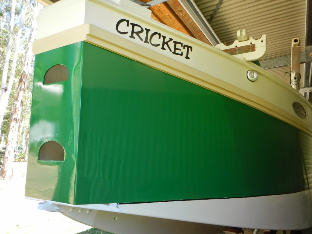
The very first Phoenix III , beautifully built by Paul Hernes
The original builder, Paul Hernes, from Caloundra, Australia, has used his boat extensively in the more than ten years since initial launching. Paul has done what I encourage everybody to do - he has continually experimented with the various rigs, making changes to the running rigging, and learning the characteristics of his boat. I am indebted to Paul for his feed-back and photos.

Another person to whom I owe a debt of gratitude is Tom Pamperin, from Wisconsin in the United States. Tom has notched up months of cruising time in a Phoenix III built by his brother, Lance. You can read about some of Tom's cruising adventures, and view his superb photos by following these links:-

http://forum.woodenboat.com/showthread.php?186576-A-Phoenix-III-in-Georgian-Bay&p=4422412#post4422412

http://forum.woodenboat.com/showthread.php?134797-A-Phoenix-III-in-the-North-Channel

More recently, Tom and a friend competed in the 2016 "Texas 200", and Tom has kindly written a nice article on the trip. It is a great story and you can see it here: -


A Phoenix III in the Texas 200

by Tom Pamperin
www.tompamperin.com

The Texas 200 is hard to describe. It’s not a race. And it’s not really a group cruise, either. I think of it as more of a multi-day endurance event for small boats: 40 to 50-mile sailing days, strong winds, tricky navigation, intense sun, remote campsites, extreme shallow water, and no shade. There’s some big water, too. Although the route roughly parallels the Intracoastal Waterway, and is sheltered from the open water of the Gulf of Mexico by a series of low barrier islands, it can get rough out on the larger bays. Conditions can be tough enough to be intimidating—or at least exciting—at times. This year, 57 boats started and 29 finished, with just 18 boats making it to every camp along the way. My brother was kind enough to loan me his Phoenix III for the trip so that my friend Pete and I could give it a shot.

Magnolia Beach, Texas—finish line of the Texas 200. (Peter Martens photo)


The sign sets the tone perfectly—this ain’t no marina cruise. Logistics for the Texas 200 can be daunting. Most sailors arrive a day early to drop off their boats at the start (Port Isabel, Texas, a tourist town near the Mexican border), and then drive their car and trailer 5 hours north to the finish line at Magnolia Beach and catch a shuttle bus back to Port Isabel that afternoon—another 5 hours of driving.


Day One: Crossing the Laguna Madre. (Jennifer Votaw Crow photo)


Our trip started out with a long day of surfing along on a broad reach to a run at 5-6 knots for 40 miles non-stop. These are typical Texas 200 conditions, with winds at 20 knots or more in the morning and getting stronger all day, all on the starboard tack. The Phoenix III handled it beautifully, with fingertip control of the tiller and no tendency to broach.

To keep things interesting, the day ended with a 5-6 mile beat up a narrow channel dredged through the barrier island forming the eastern edge of the Laguna Madre, with the campsite located right on the edge of the Gulf of Mexico. More than a few boats quickly abandoned the attempt to beat up the channel; for us in the Phoenix III, it was a simple series of tacks through steep chop—a bit wet, but we never missed a tack and stayed perfectly in control. Pete shot a bit of video at the camp that night to give his family some idea of what the Texas 200 is all about:

On the beach at the Port Mansfield jetties. (Peter Martens video)


 Day Two: More of the Laguna Madre. (Peter Martens video)


More of the same for day two—big wind, broad reach to a run. Continue for 8 hours. Pete shot the brief video on his IPhone while we were surfing along. He’s done some Hobie sailing back in Wisconsin, but I don’t think he had ever seen this kind of sustained surfing before.

Day Three: Northward to Bird Island. (Matt Schiemer photo)


 The photo above shows the campsite for the evening of day three near Bird Island, just outside of Corpus Christi. Another 40 miles on a broad reach to a run to get here—with a side trip to the barrier islands. At one point we were completely surrounded by porpoises, who started launching themselves into full-on aerial leaps all around us. Pete and I were laughing out loud. Later on we “parked” the boat to wait for a sailor who had fallen behind by simply letting the sheet run free, letting the sail weathervane freely while we drifted slowly and peacefully to leeward, broadside to the wind—a nice feature of the Phoenix III’s balance lug rig. 


Day Four: Pete at the helm, entering Corpus Christi Bay.


 The low sheeting loads on the lug rig make expensive blocks and hardware unnecessary—we simply ran the sheet around a horn cleat on the leeward quarter, forward to the oarlock, and back to the helmsman’s hand. Another advantage of such a simple arrangement is that the sheet can be kept much shorter, leaving less line to tangle around the crew’s feet. We also sometimes ran the sheet through a ring on a simple rope traveler over the tiller, another cheap and easy method that’s a bit handier for gybing.

The winds finally relented a bit—down to 20 knots, maybe—so we spent the day under full sail. Today brought the big water and long fetches of Corpus Christie Bay, so we hugged the windward shore, sliding through narrow channels along and around the barrier islands, sailing in water so shallow that, board up, the keel was dragging through the mud. “Deep water” on the Texas coast means water that might get your knees wet if you stepped overboard.

Later in the day we could have cut back into the deep buoyed route of the ICW, but there was a better option for boats like ours: Corpus Christie Bayou. We simply ignored the marked channel and sailed up to a crumbling ramp at the edge of a bridge, lowered the mast to row through, and re-hoisted the sail. From here the route to camp was an exercise in extreme shoal-water sailing, trying to find a twisting channel which had shuffled itself outside of its own markers, forcing us to guess where deeper water might be found.

Again, not a problem in the Phoenix III. Since the channel wasn’t reliable, we simply cut across the flats, sailing along in water so deep that the keel (board up) was once again buried in the mud. We only had to get out and pull the boat along for about thirty yards, and we were through to deeper water and the oyster-shell beach of the Quarantine Shores campsite.


 Camp at Quarantine Shores—plenty of home-built boats, and not much else. (Peter Martens photo)


Day Five: Sailing through the night. (Bill Fisher photo)


Light winds, for Texas at least. We spent the day on a broad reach under full sail, still doing between four and five knots. In the afternoon the winds picked up, shifting eastward far enough to put us close-hauled—the first time since day one that we hadn’t been on a broad reach or a run.

The day ended at Hidden Pass, where we sailed through a cut almost narrow enough to jump from island to the next—with a running start. Maybe. I couldn’t get Pete to try it, so we’ll never know for sure. We did find an alligator skeleton on the beach, so perhaps his reluctance to risk a swim was well-founded.

At camp that night, everyone with radios and smart phones was talking about tomorrow’s weather forecast: very hot, with light winds. “It might not be the dumbest idea to just keep going through the night,” I told Pete. True, there’d be some tricky navigation getting through one of three marked cuts into the next bay—but the moon was nearly full. And we had a good breeze now. It would be a pleasure to sail while it was cool for once; we had been decked out in long sleeves and long pants for days, trying to protect ourselves from the fierce sun.

And so we hung out with the fleet at camp until sunset—right around the time that mosquitoes would have forced a retreat into tents anyway—and then set out across Espiritu Santo Bay, the last big water of the trip. Perfect sailing! A nice 15-knot breeze, cool air, and the fierce red eye of the sun hidden safely below the horizon. I was surprised no other boats came along, but I guess they wanted to see how we did before they tried it for themselves. Maybe next year it’ll become a popular strategy.
The winds picked up as we went, and then suddenly fish began popping out of the sea all around us. Quite remarkable—they would hurl themselves straight up, four or five feet into the air. One of them even jumped overthe foredeck.

Then one of them jumped into the boat. And another. Using a boat cushion, I scooped them down toward Pete, who had his hands full already with the tiller and sheet. “Fish in the boat!” I shouted as another one threw itself aboard. “Fish in the boat!” He threw them overboard one by one and mocked me for my timidity. I kept wielding my cushion and pushing them his way.

The rain of fish kept on for half an hour. They were mullets, sleek silvery fish half the length of my forearm, and were no doubt being pursued by bigger, hungrier fish. Porpoises, perhaps. I sympathized with them, but still, I wasn’t letting them stay aboard.

By the time we reached the far shore of the bay on our moonlit sail, we weren’t sure of our exact location. I don’t carry a GPS (I cling to a stubborn curmudgeonly belief that such devices remove many of the rewards of sailing, and make us less skillful and less aware), so we had steered a compass course designed to take us far enough south of our goal that we would know to turn north when we hit the shore.

It worked, kind of. Bumping along northward through the shallows, using the centerboard as a depth sounder, we followed the far shore of the bay until a vague cluster of lights showed up ahead. Somewhere near there would be our cut. We passed a marker buoy from the ICW, but weren’t able to locate the channel itself in the darkness. And then suddenly we had land on both sides of the boat, a development that was difficult to reconcile with the chart, using a tiny red headlamp as the waves tossed the boat this way and that. But eventually, despite the first faint stirrings of seasickness, I was able to get a pretty good guess at where we were.

Which proved wrong in the next moment as we discovered a buoyed channel cutting directly across our path: it was the last of the three channels we had been looking for, and we had found our way successfully through the darkness.

The rest of the night was a quiet sail northward as the winds gradually dropped away, until around 4 a.m. we coasted up onto the beach under oars. Magnolia Beach. If the Texas 200 had been a race (it isn’t), we would have just won. Then again, given how much we had enjoyed our nighttime sail, we had won. Everyone else would be bobbing and baking in hot sun and no wind for hours. Pete and I pulled the boat ashore, set up our tents, and enjoyed a few hours of sleep in the cool air of the morning.


Conclusions: A very good boat. (Peter Martens photo)


 The author and his brother’s boat at the finish line: the beach at Magnolia Beach.

Judging by the results—57 entries, 29 finishers, and only 18 boats (including us) making it to every campsite— this year’s Texas 200 was a tough event for a lot of people. For Pete and me aboard the Phoenix III, it was a pleasure cruise. I’ve put a lot of miles on my brother’s boat, and the more I sail it, the more I like it. Anything I’d be brave enough to try in a small boat, I’d be happy trying in a Phoenix III.

I’ll end by explaining a few of the features of the design that I have really come to appreciate. These may not all be the things that come easily to mind when you’re new to this kind of sailing—they are instead appreciations that have evolved gradually, after many hundreds of miles of cruising under sail and oar, rolling the boat up onto beaches, anchoring off and sleeping aboard, the whole spectrum of cruising life. In short, these are the things I didn’t know enough to want from a boat until I had put in some sea miles.

1. The simple balance lug rig is easy to reef, easy to strike for rowing, docile and well-mannered in use (gybing is particularly simple and stress-free), and allows you to “park” the boat by simply letting the sheet fly so the boat drifts quietly broadside to the waves. It’s also easy to raise the sail anywhere on the starboard tack (if you rig with yard to port as I do)—no need to hold the bow precisely into the wind as on a Marconi rig (and thus no need for the complications of a mizzen). And the mast is simple to drop if you need to slip under a low bridge.

2. Capsize recovery. My brother and I tested this on a windy day (20 knots+) and found it EXTREMELY difficult to capsize this boat, even on purpose. But when we did (after leaning 400+ pounds over the leeward gunwale for 20 seconds), it was easy to right and re-board—so easy I’m confident I can do it for real if the situation ever comes up. And the centerboard design puts the top of the case well above the water level, meaning the boat can be bailed dry without taking in more water through the case.

3. Sleeping platform. The optional set-up for sleeping aboard works well for two sailors, and is luxurious (by backpacker standards) for a solo sailor. Simply carry an extra plank under each side bench and the entire width of the boat becomes a comfortable sleeping space. A simple tarp on a line from mast to rudder head makes a good boom tent to keep you dry. I’ve switched almost entirely to sleeping aboard because of how simple and comfortable it is.

4. Good rowing performance. The Phoenix III is no racing shell, but I was able to outrun a Hobie with a pedal-powered Mirage drive for an hour while rowing at a pace slightly faster than my all-day endurance pace. This boat makes rowing a pleasure rather than an ordeal.

5. Good windward ability. Gentlemen don’t sail to windward—except sometimes you have to. The Phoenix III keeps up good speed and points well, and the fine entry and wide gunwales make it a fairly dry ride.

6. Glued lapstrake plywood construction. I’d rather be sailing than sanding and fairing, and lapstrake is probably the quickest and most pleasant route to get there if you’re building a new boat. It also makes for a stiff, strong, lightweight hull.

But the best feature of the Phoenix III—a quality I have not often seen to this degree in other designs—is less quantifiable: it’s just right. The layout and proportions feel natural; it all works, in a very practical and user-friendly way. This is a boat that seems to have been designed by someone who actually goes cruising, and has thought a lot about what works and what doesn’t. The thwart divides the boat neatly into stowage (forward) and living areas (aft). The anchor bucket fits easily along the forward bulkhead alongside the mast. Large duffel bags stow neatly alongside the centerboard case, held in place under the thwart—it’s much easier to carry a couple of bags ashore than it is to dig through small hatches. The bags also increase flotation if the boat is swamped or capsized.

In fact, the ergonomics of this boat work so well that even two large (6’ 2”) adults can fit comfortably aboard for a long cruise. And sailing solo, the helmsman can slide fore and aft along the side benches, moving all the way forward to the thwart for windward work, and sliding back to the sternsheets for running, keeping his weight right where it needs to be.

And because the centerboard is designed so that it does not intrude on the helmsman’s space (after experiencing this, I’ll never accept a cruising boat without it), it is VERY easy to switch sides when tacking and gybing. This is something you’ll do hundreds of times (if not thousands) aboard a cruising dinghy, and it is a simple and enjoyable move every time on the Phoenix III.

All in all, I haven’t seen a boat I like better for sail-and-oar cruising. I doubt I ever will.


Lugsail Yard Parrels

$
0
0
My old boat setting a balance lug, with the yard snugged up against the mast

 A problem which many people encounter when using a balance lug, standing lug, or a Chinese lug, is arranging a method to hold the yard close to the mast.

Some designers advocate a method where the halyard is attached to the yard towards the heel, and then leading along the yard (and around the mast) to a pulley-block at the normal halyard attachment point.

The theory is that as tension comes onto the halyard, it automatically pulls the yard in against the mast. I've tried it, and (for me) it doesn't work. The amount of force holding the yard against the mast is small, and much more importantly, the yard is largely free to move forward and aft through a significant arc.

Here are two photos taken on a day when we tried it on my sailing canoe just for fun, and as you can see, it wasn't worth a cracker!

Yard with the normal halyard attachment point hanging aft by close to a foot

Halyard doing a very poor job of holding the yard close to the mast, even though the downhaul and halyard tensions were high.


Another popular option is to use a loop of line, bronze rod, or stainless-steel rod around the mast somewhat like a conventional mast hoop on the luff of a gaff mainsail. If you follow Jim Michalak's suggestions for a loop of line, it will work OK, but is prone to jamming when the sail is raised. You can confidently follow Jim Michalak's advice about almost anything regarding boats, but in this case I believe there is an even better way.

The metal ring method has problems in that it makes it very difficult to get the yard aft when lowering, until you can reach high enough to lift the yard off the hook which usually forms the attachment to the ring. If the sail is boomless, it may not be too much of an issue - but when a boom is involved, it is very important that the yard is free to move fore and aft while still being attached to the halyard.

The system I prefer is simple, light, and highly effective. Here is a drawing which should be self-explanatory. Click on the drawing for a clearer view.


The loop (shown in red) can be simply dropped around the halyard, or can be attached to the yard by the halyard rolling-hitch. Raising and lowering the sail is no problem, because as soon as the yard is lowered, the loop automatically loosens, and when being raised, the loop is loose until the yard reaches the raised position. If you need to reef, lower the yard to the required position, and simply re-tighten the lower end of the snotter (a.k.a. Yard Parrel) and the yard will be held snugly against the mast. No need to make it tight - just snug.

Below are two photos showing the system in use on a First Mate. In this case, we had the snotter line knotted into the halyard rolling hitch on the yard, but it isn't necessary - the system shown in the previous drawing is fine.

Blue line is the halyard, and the buff-coloured line is the snotter (yard parrel).


The system is simple, light, and reliable. I've used it for years without any problems.


Up-date - Lugsail Yard Parrels

$
0
0
In my previous post, I presented a hand-drawn illustration of my preferred method of setting up a yard parrel (in this case a Snotter).

The drawing shows the parrel/snotter (drawn in red) simply slipped over the mast and the halyard, but in the text I mentioned that the parrel can be attached to the rolling hitch which secures the halyard to the yard. For the entire time - at least three decades - that I've been using this parrel system, I've always secured the parrel to the halyard or the yard, but when I was preparing the drawing, it occurred to me that it may work simply slipped over the mast and the halyard.

Well, just two days ago I did a rigging job for a man who had built a beautiful Paul Gartside-designed lapstrake (clinker) dinghy. In the process I tried out the method as depicted in the above drawing, and although it worked, the parrel had a tendency to hang-up on the mast due to friction between itself, the mast, and the halyard. I quickly re-rigged it so that it ran under the rolling hitch, and everything was fine.

So lightly attach the snotter to the yard or the halyard where it is secured to the yard. That way, the parrel/snotter will lower positively with the yard.
Viewing all 78 articles
Browse latest View live