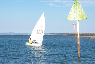
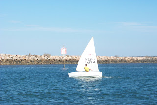
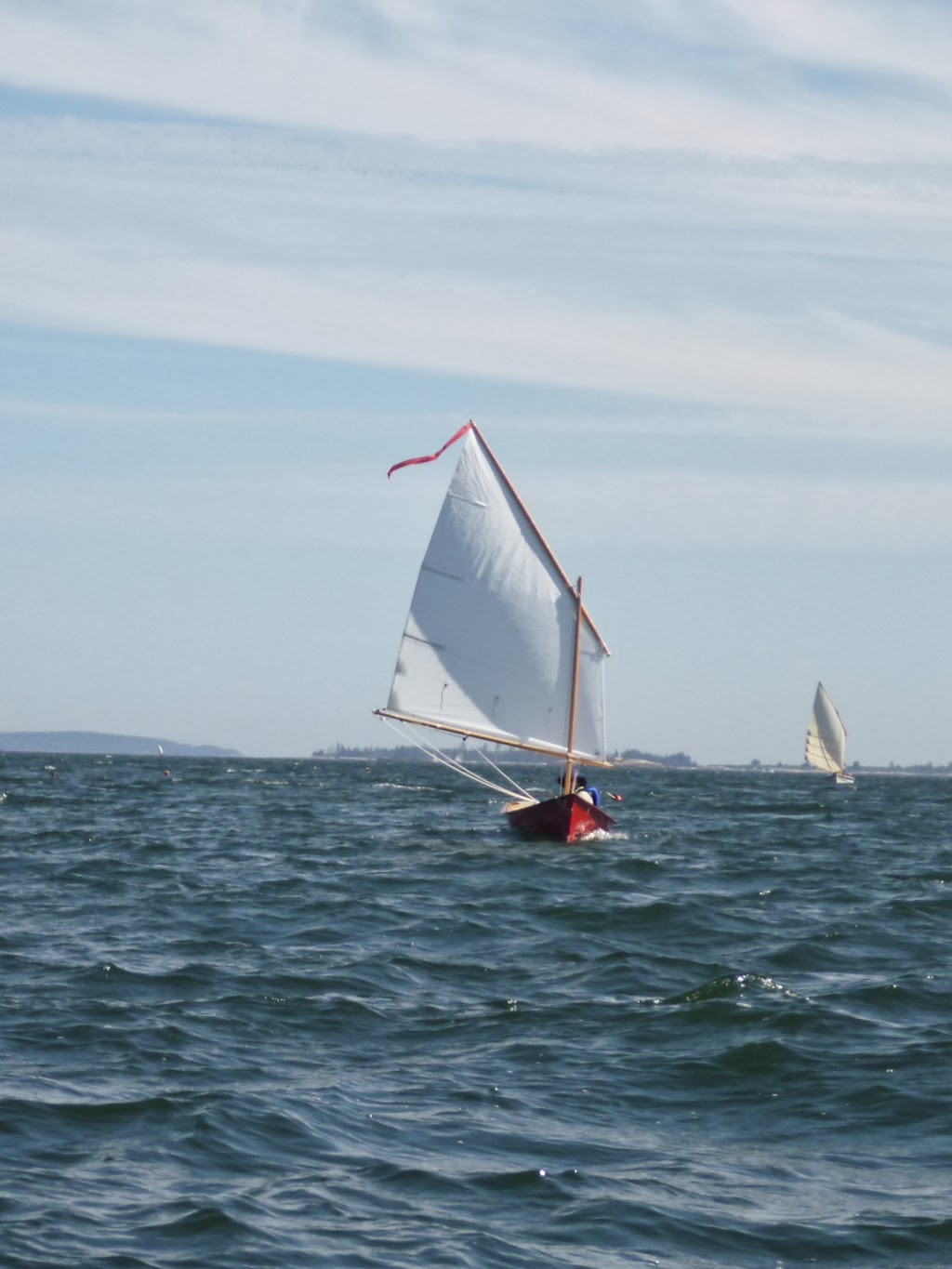
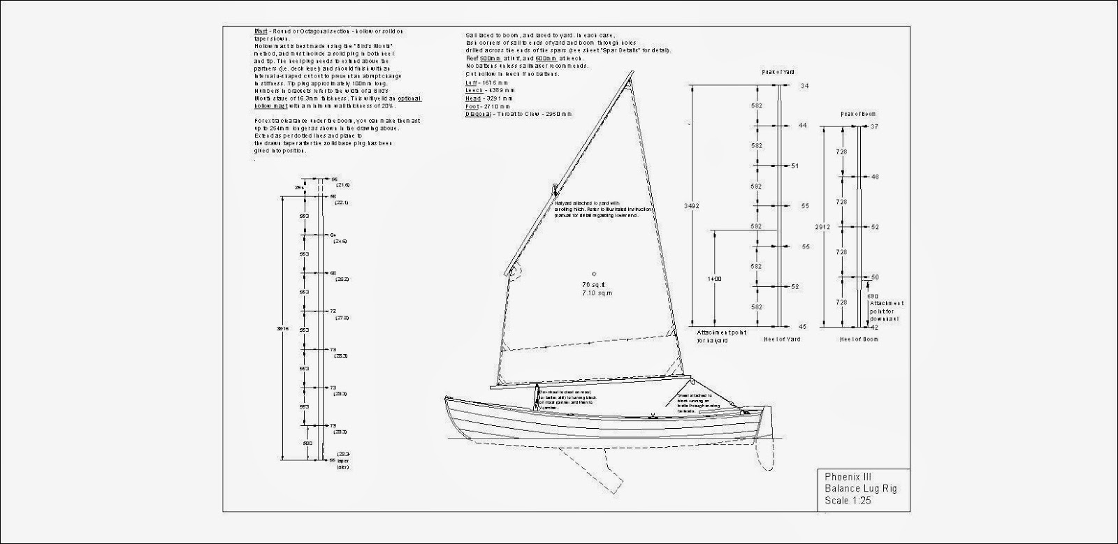
It was getting close to 5pm as two small sailing boats luffed up into the easterly breeze which although moderating a bit, was still fresh and blustery. As the sails snapped and flogged, one person from each boat dropped over the side into knee-deep water and each grabbed hold of a boat by the bow.
In the bigger of the two vessels, Mike Rowe quickly released the main throat and peak halyards and the mainsail dropped neatly into it's lazyjacks. Already the small jib was rolled up around the wire-reinforced luff which also served as the forestay, leaving the boat with a single sail standing on the mizzen mast which pierced the aft deck adjacent to the stern transom. This mizzen sail was undoubtedly a complication to the rig, but Mike knew it was superbly practical, and paid it's way handsomely. Right now, the mizzen sail was sheeted in tightly, and was holding the little yawl securely head-to-wind.
Having come to a halt a short distance away, the 15-foot sailing dinghy which formed the second boat in the fleet, was also being stripped of sail by her young skipper, although he did not have to trouble with a mizzen. He conducted his sail lowering operation one-handed by leaning over the deck of the boat while keeping hold of her bow with his remaining hand.
Mike and his two sons were feeling the effects of a long day exposed to the elements. They had started early from a roadside camping area, arriving at the launching ramp mid-morning. As usual for people with busy lives, it had taken some time for them to sort their belongings and the ship's stores, so that by the time both boats were afloat, loaded, and tow vehicles safely parked, the sun had passed it's zenith. However, although the travelling and loading arrangements took a while, the operation of the two boats was efficient and neat. This was due to a combination of design, development, and experience. Not one of the three was a slave to fashion.
So, at the risk of boring some readers, but hopefully passing on some useful information to others, here are some details.
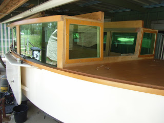
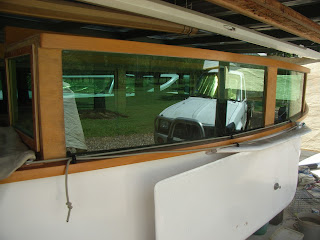
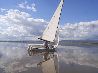
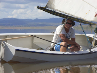
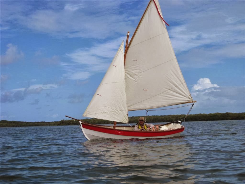
The larger of the two boats was a V-bottomed plywood yawl of 17-1/2ft length-on-deck, sporting a transom bow (i.e. a praam or scow hull - blunt at both ends), and a small cabin whose sides extended to the gunwales. She had a large cockpit with wide side seats and a small, watertight and self-draining foot-well. Down below the cuddy-cabin was unusually voluminous and airy for a boat of such modest overall dimensions (17ft 6ins by 6ft 10ins), due to the cabin sides extending to the gunwale, and most importantly, because of the transom bow. This made her usable space comparable with that of a conventional boat four or five feet longer.
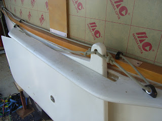
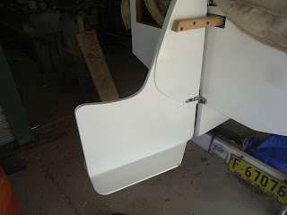
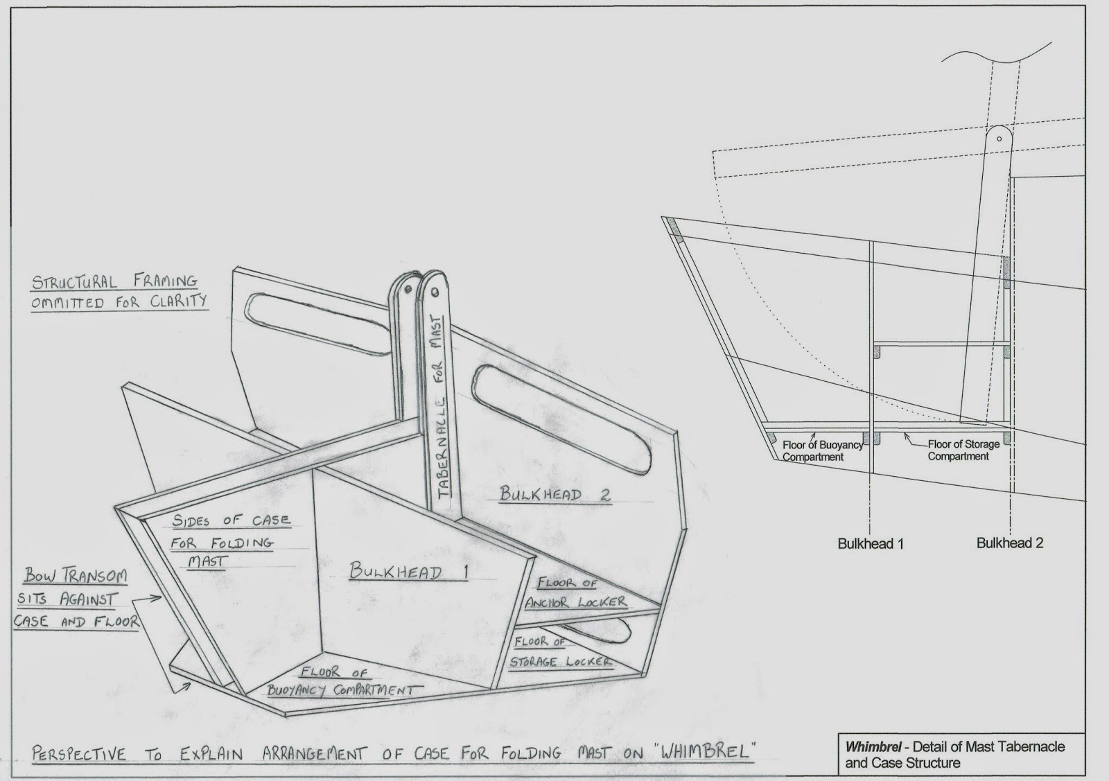
In terms of volume, the shape of the boat was a really important factor, but what made her interior particularly open and uncluttered was the total absence of a centreboard and centreboard-case. Instead of a centreboard the small yawl carried a pair of leeboards slung externally on each side. Many people understand that leeboards are very effective and efficient as a means of providing lateral plane for getting to windward and for reaching, but it is less well understood that certain hull shapes are better suited to leeboards than others. This little cruiser's hull was close to ideal for leeboard use, and in many ways was similar to that of the wide, shallow craft of the Netherlands and Germany where leeboards are so common.
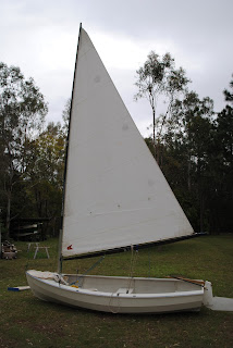
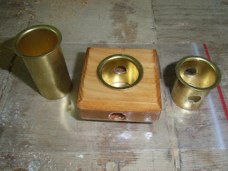
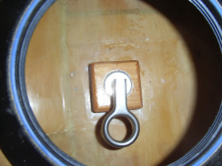
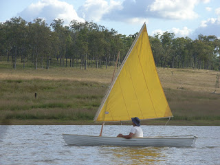
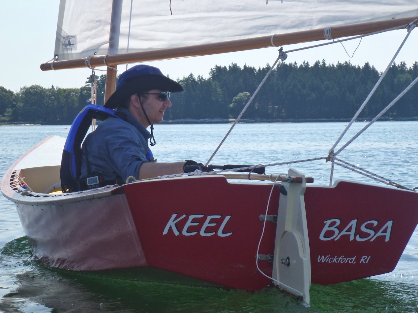
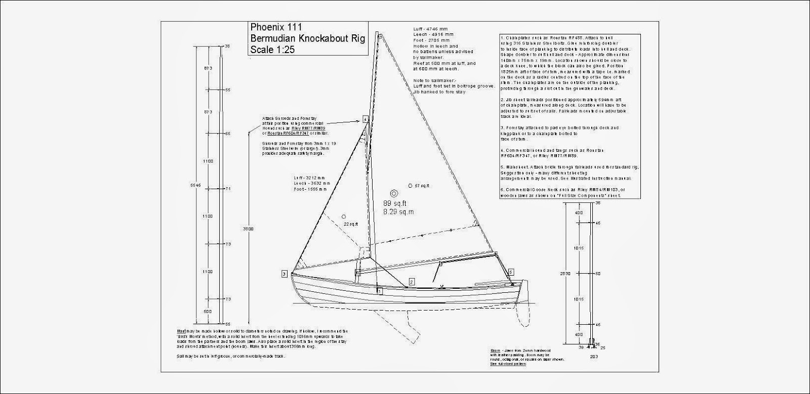
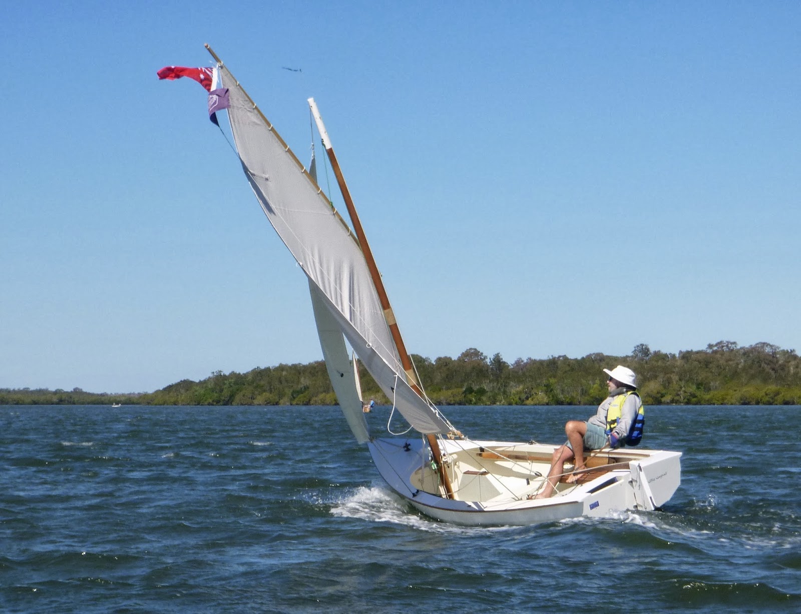
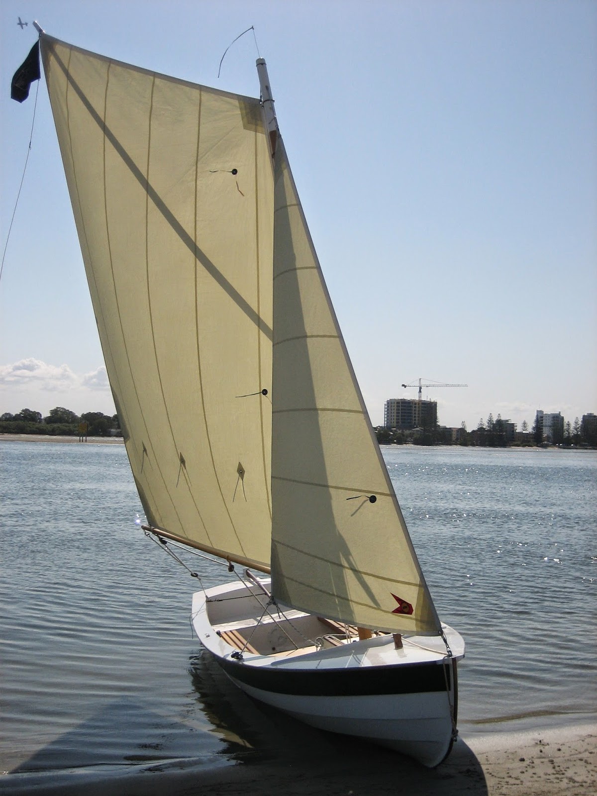
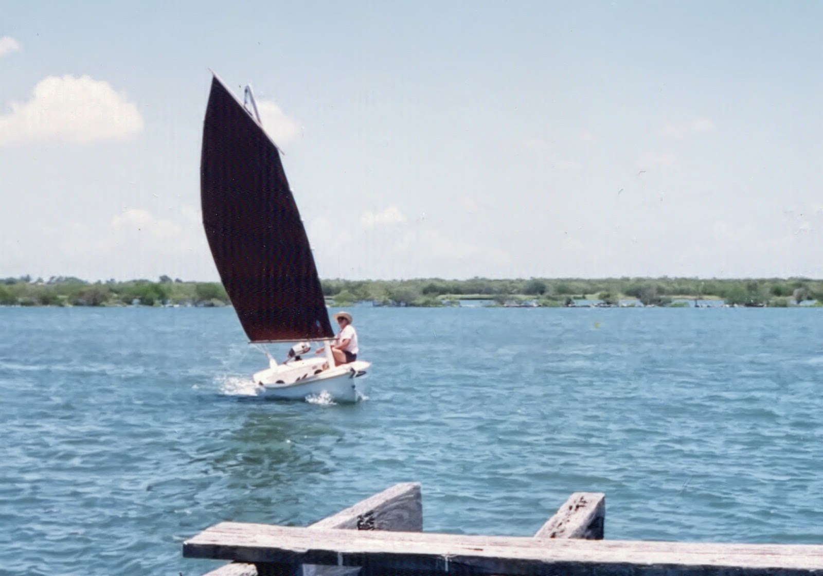
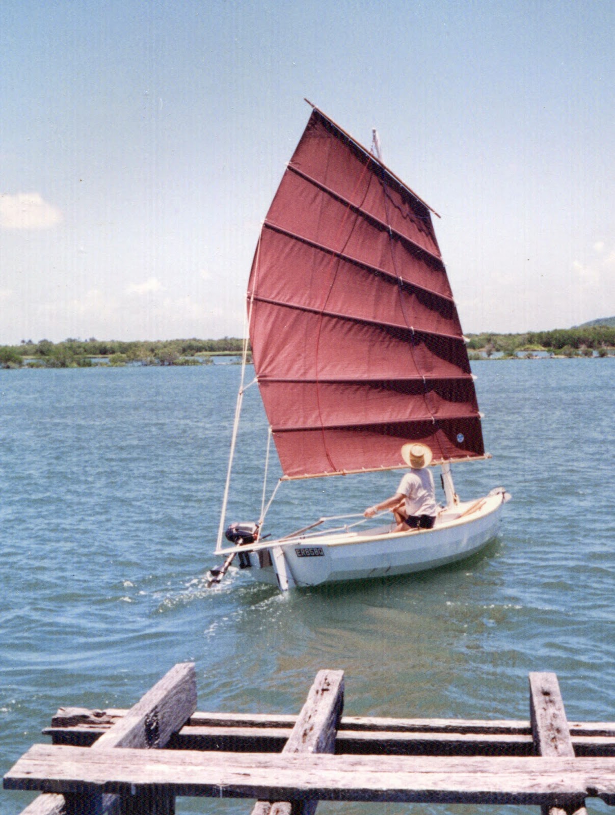
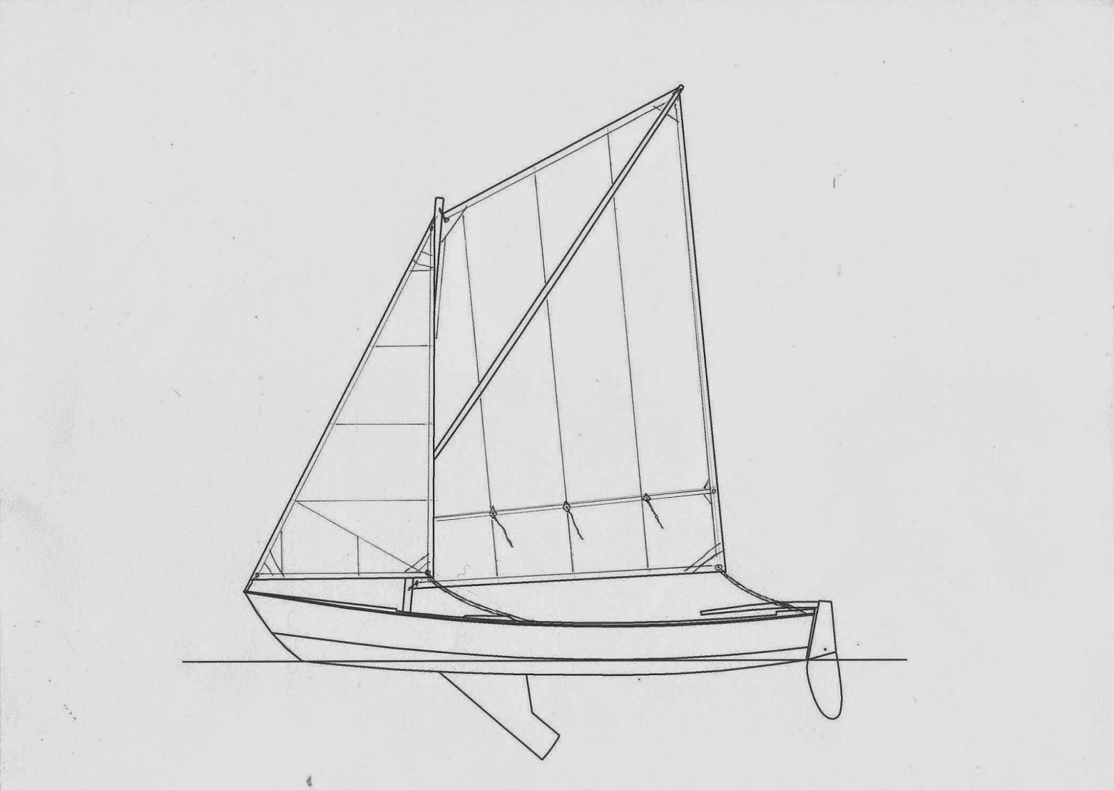
The other boat was a light sailing dinghy of 15ft by 5ft, sporting a short, free-standing mast which supported a sprit rig of generous proportions and a smaller flying jib. The boat was set up specifically for cruising, with a useful galley box wedged under the main thwart, and substantial ground tackle (i.e. anchor, chain and rode) well located between the forward bulkhead and a purpose-built semi-bulkhead.
Large emergency buoyancy tanks were built-in under the fore and aft decks and also under the large stern sheets (rear seat). The emergency buoyancy, combined with the light-weight hollow wooden mast, meant that this boat was fully capable of self-rescue. So far on this boisterous trip, the young skipper had kept the jib stowed, and had a reef tied in the mainsail.
Having done a temporary stow of the sails and setting light anchors in the shallows, the three headed up the beach to stretch their legs and to have a snack at the tree line. That idea lasted about two minutes before the cloud of mosquitoes and midges sent then on a hasty retreat to the relative safety of the water. Piling into the larger boat, Mike and Geoff upped anchor and allowed the breeze to blow them back into deeper water. Mike then lowered the small outboard (a two horsepower air-cooled Honda four-stroke which weighed only 12.5kg) and motored to a spot where they could ride out the night regardless of the state of the tide, and the strength of the wind, as long as it stayed anywhere from a north-westerly around to a southerly. Mike felt confident they would have a safe night.
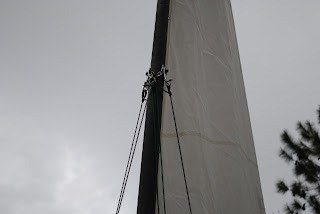
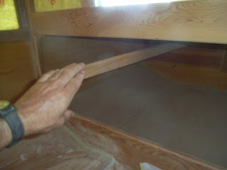
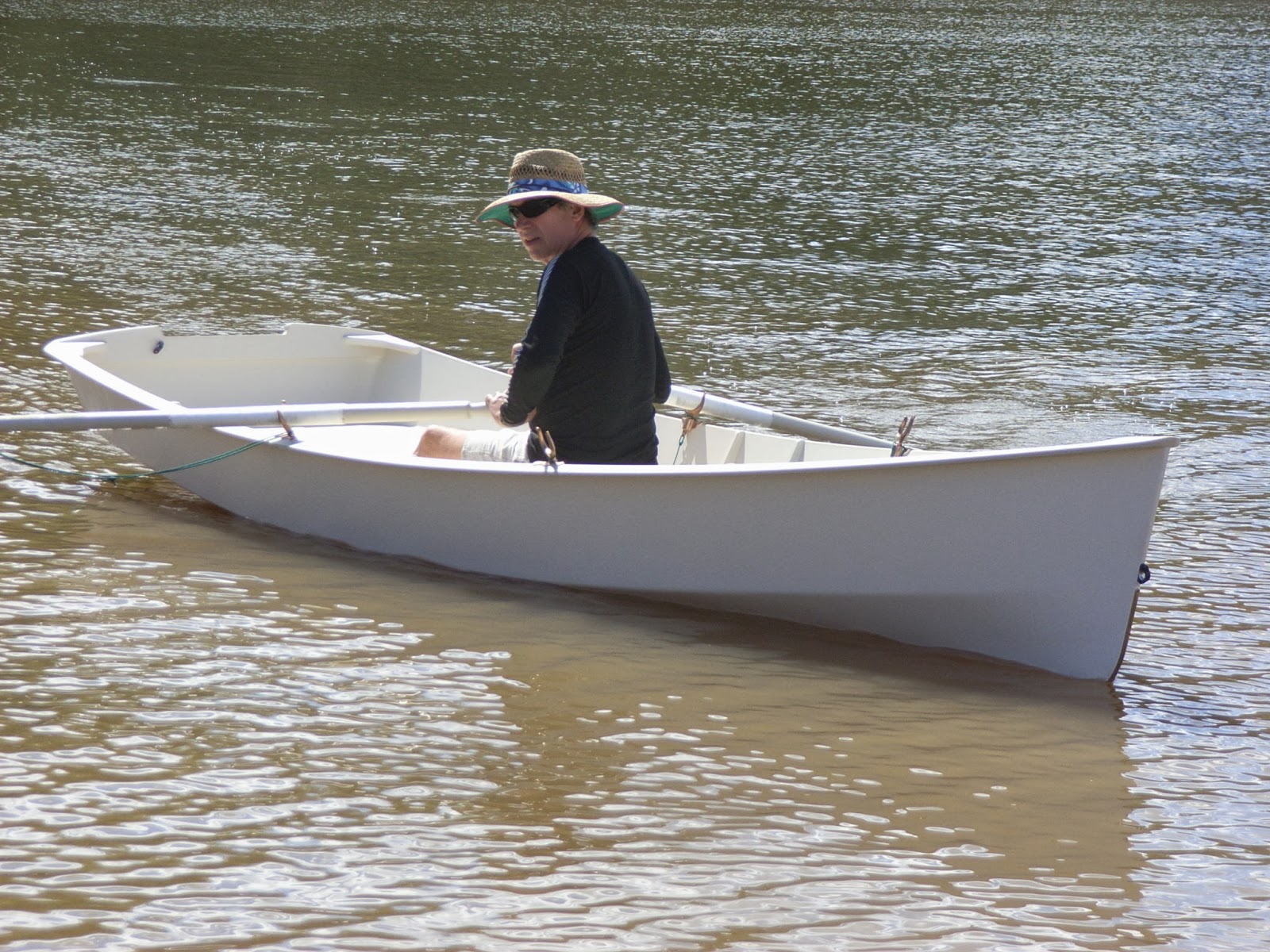
With the anchor set and the anchor rode safely wrapped with padding where it ran through the bow chocks, Mike and Geoff looked up to see Dave rowing towards them in the sailing dinghy. Knowing just how important it is to reduce windage when rowing, he had lowered the mast, which lay to one side in a bundle with the sail and sprit. Because the mast was free-standing, lowering had taken him no more than thirty seconds, and he was enjoying the sensation of rowing a boat which had been designed with the rowing thwart in the correct place and height. Dave had made the oars with his own hands, just as he had the boat and spars, so the whole operation was filled with pleasure and satisfaction.
![]() |
| Mike and Dave leathering home-made oars |
Leaning over the stern transom of the yawl, Geoff made the sailing dinghy's painter fast to a cleat on one side of the aft deck, while Dave grabbed the gear required for a night aboard the mother ship. The two boys worked together to set a boom-tent under the bundle of sail and spars, all well supported by a topping lift and lazy-jacks. The boom tent was a very simple affair, being a four-sided piece of fabric with a series of ties sewn along the centreline. These were passed over the sail and spar bundle and tied off with reef knots. Once the outer edges had been laced onto the line of hooks under the gunwale moulding, there was a large tent over the cockpit seats, allowing all three to sit protected, and giving Dave his own bedroom as he slept on the cockpit seat for the night.
![]()
A key to the success of the boom tent was the fact that the forward end extended well past the aft end of the cabin. This meant that even during periods of rain, the cockpit remained fairly dry, while lots of air was able to come in to ventilate the living space. Mike really enjoyed the sensation of being under the boom tent, or inside the cabin, while rain drummed down at the end of a hot summer.
All three were ready for sleep, even though it was still only evening. An early start, salt-air, exercise, and sun had all combined to produce a feeling of healthy exhaustion. Mike was aware that food was important in this circumstance, and he also encouraged everybody to use fresh water and towelling to wipe encrusted salt from their faces. It is amazing what a morale-booster it is to get the salt off, even if it is just the face.
Food was simple to prepare. Mike sat on the end of one of the bunks in the cabin, and passed out some large cans of beef and vegetables. He was very careful to select high-quality canned food for these trips, and had discovered that many of the better companies were offering the option of low-fat and low-salt menus. Normally, he removed the paper labels and wrote the name of the contents directly on the can using a felt-tip pen. They all drank a good amount of water, and Mike also downed a couple of glasses of red wine in a contented fashion.
The plan was to meet up with a friend and Mike's third son prior to lunch the following day. They were following in a long, slim powerboat that Mike had designed for his friend, but they had been delayed by transportation issues. However, the speed of the powerboat meant that their trip from the boat ramp would only take an hour-and-a-half, so all would be well.
Meanwhile, our three adventurers were settling down for the night - Mike and Geoff comfortably arranged on their individual bunks below, and Dave, already asleep, on a sleeping mat on the port cockpit seat.
The occupants of the boat slept soundly, and elements of the design of the boat aided in the sleeping process. Firstly, the bunks in the cabin were a full 24 inches or 610mm wide for their entire length of 6ft 6ins or 1981mm. It is usually said that a bunk should be at least 22 inches wide, so for such a small boat, the bunks were exceptionally well proportioned. This was made possible because of the transom-bowed shape of the boat. Secondly, the boat design incorporated a large vent in the forward cabin bulkhead, and this vent was baffled so as to allow a full flow of air, but keeping rain and spray out. Mike was astonished at the large number of boats which had stuffy cabins because of poor ventilation.
Lastly, although the boat had a very shallow vee-shape amidships, the bottom panels twisted significantly to produce a vee of 32 degrees deadrise in the forward sections. This meant that the drumming of wavelets under the hull was reduced to a pleasant lapping sound, which seemed to help true sailors descend into a deep and healthy sleep.
Next day promised to be exciting, with a convoy of three boats and the likelihood of some serious exploration.
Morning sunlight was flickering and reflecting off the paint inside the cabin as Geoff woke the next day. He could see his father quietly reading as he lay on the bunk opposite, and it was only then that Geoff started to take notice of the stowage arrangements in the boat. The previous day had been too busy for him to be aware of such details.
Behind Mike's head as he lay on the bunk (i.e. forward in the boat) was a low bin formed by a semi-bulkhead at the head of the bunks, and the main cabin bulkhead 11ins (278mm) further forward. This bin was 7ins (176mm) deep and 4ft 10ins (1474mm) wide. The bottom was formed by the vee-shaped bottom of the boat. Geoff noted that it currently held things such as a hand-held GPS, a couple of rolled up charts, two PFD's and a dry-bag which he assumed contained things like his father's car keys, wallet, and camera.
Moving his glance further forward, Geoff noted two cut-out openings in the lower part of the cabin bulkhead which lead into more stowage spaces. It turned out that big storage bin behind the openings was 9-1/2ins (246mm) high by 4ft 10ins (1474mm) wide, and 11ins (278mm) deep. Plenty of handy space for loose items that would be needed in the cabin.
Just then his old man's smiling turned towards him, and he knew it was time to start having some fun on the water!
Geoff clambered out of the cabin of the small boat and sat under the boom-tent in the roomy cockpit. On the cockpit seat opposite, his brother lay asleep in his bedding, squinting each time a small patch of sun passed across is closed eyes. Looking aft from under the boom-tent, Geoff could see that low tide was once again approaching, and a fringe of mud lay between the blue water and the green of the hillside. Being an impulsive sort of a person, Geoff was tempted to dive over the side for a morning swim, but the combination of an unknown water depth and the possibility of lurking crocodiles made him think better of it. Reaching over the transom, he swept a handful of salt water over his face and flicked the remainder at his sleeping brother.
Down below in the cabin, Mike Rowe was attending to far more important matters. His home-made galley box was open and a dual fuel stove was already beginning to boil water for his morning coffee. While the water was heating, Mike had been perusing the chart covering the day's proposed trip. The idea was that Mike's third son, Steven, would join them that morning along with their family friend, Ian, both of whom should already be on their way to the anchorage aboard Ian's powerboat. The convoy of boats would then head north-east and east for about 35 km (19 nautical miles) to their final camping destination. Because Ian's boat would be so much faster than the two sailing vessels, Ian, with Steven and Geoff aboard, intended to detour about 10 km offshore to investigate a rocky island which he hoped to climb in the coming days.
For the next hour and a half, Mike attended to housekeeping jobs aboard the boat while Geoff and Dave explored the nearby coastline, having rowed ashore in Dave's boat after a hasty breakfast. He left the boom tent erected so as to protect himself from the tropical sun which was already making itself felt despite the early hour. Just as the others returned to the boat and Mike placed himself against the main bulkhead to drink his second cup of coffee of the day, they all heard the sound of a distant outboard motor. It appeared that for one of the few times in his entire life, Ian was on time.![]()
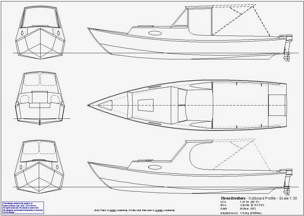
Mike dived below and quickly returned with a set of binoculars and rapidly trained them on the approaching boat. Although he had been out on the boat himself several times, this was the first opportunity he had had to observe her action in open waters. There was a moderate sea running in from the north-east and he was interested to see how the boat would handle a quartering wave pattern. Although she was fully 26 feet long, her 6'6" beam made her a much smaller boat than most people would have imagined. Mike had designed her at Ian's request, and both men were very keen to gather information about her performance. The pair shared the opinion that the majority of planing powerboats are overpowered, overweight, and designed to operate at speeds which are rarely practical on open water. The boat which Mike had designed for Ian represented a strenuous attempt to produce a boat which was both economical to operate, and economical to build.
Three Brothers as the boat was known, had been proportioned to operate most effectively at a speed length ratio of 2.2, which in this case is a speed of 10.5 knots or 19.5 km/h. As part of the design process, Mike had produced the following performance estimates for Ian to think about: -
· Displacement 0.82 tonne including 288kg of passenger weight
· LWL 22.6 ft
· Power to achieve 10kts - 13.9hp
· Power to achieve optimum SL ratio 2.2 - 15.6hp
· Speed with 30hp (Crouch’s Planing Speed Formula) - 19.3kts
· Speed with 40hp (Crouch’s Planing Speed Formula) - 22.3kts
· Speed with 50hp (Crouch’s Planing Speed Formula) - 25kts
Ian's boat was being powered by a 30 hp two-stroke Yamaha outboard with three cylinders in-line, for the simple reason that this was the engine he already had. It had originally been his plan to purchase a four-stroke motor of about the same power, but the current one was performing so well that he no longer saw the need to change. Although the boat could achieve the 19 knots predicted, Ian normally throttled back to cruise at about 12 knots, a speed at which both the engine and boat felt comfortable, with the lean and sharp hull cutting through waves without pounding.
After meeting up and swapping gear, crew members, and stories, the flotilla set off for their destination. The skippers of the two sailing craft were both avid sailors who enjoyed the technical side of the sailing and never became bored along the way. The remaining three in the powerboat were made of different stuff, and relished the thought of a run out to the off-shore island prior to heading into the camping spot for the night.
Now, there will be some among you who say that ten or twelve knots is not very fast, but let me tell you it is a lot faster than any sailing most of us will ever experience. Yes, I know that we've all had rides on catamarans or skiffs which have travelled fast on a particular point of sail, but taken over over a number of trips, not many people can truthfully claim an average of more than four knots. This takes into account calms, tacking, adverse tides and other things. There is no doubt that if you are on a schedule, a powerboat is what you need, and twelve knots (22km/hr) will get you over a lot of water in a day. The high-speed planing boats with huge, fuel-guzzling motors might get you there faster if the weather is kind, but will you be able to enjoy the scenery and ride? Not in my experience.
The path our powerboat crew took ended up being about 42km, so excluding exploration their journey time was 115minutes. On the other hand, Mike and Dave, would probably have averaged 3 knots given tacking and an adverse current, so their 35km would have taken 380 minutes or nearly six and a half hours! In fact, for about half of the distance they both ran their outboards and then sailed when the wind increased and the point-of-sail improved to give them an average speed of 5.5 knots - so 3.4 hours for the entire trip.
Both crews claimed to have enjoyed the day - the powerboat people having explored the island for a few hours and done some fishing, while the two sailors relaxed at their sport, enjoyed the challenges, and ended up getting to the destination first. Had the sailing boats not had auxiliary motors, matters would have been different.
Later that evening, Mike and Ian sat on the beach in comfortable director's chairs which had cost $26 each at a local hardware in Mike's town. In years gone by they would both have shunned such luxury, but nowadays they enjoyed the indulgence. The pair were drinking strong coffee laced with a liberal shot of brandy, and were feeling philosophical given the bottle of shiraz they had shared at dinner. The current subject was power-boating in a cruising context, and the data gathered from the last twenty-four hours was fresh in their minds.
"I used to think," said Mike, " That powerboats were nautical appliances - something used to get a particular job done in a certain time. But now I'm not so certain. That boat of yours is quiet, smooth, economical, and relatively speedy - and there can be no doubting the fact that the ergonomics are better than my sailing boat and Dave's." After thinking for a minute or so Mike continued, "But then again, there is a lot to be said for motor-sailing the way Dave and I did today. We avoided being bounced around in the left-over slop when the wind dropped out, but we were able to sail in a satisfying manner when it breezed up about eleven o'clock. We had a good sail, while you had to put up with being a powerboat all day long."
Reaching for a refill of coffee and a splash of brandy, Ian replied, "Yes, you may be right about the motor-sailing, but because we were in a proper power-boat, we had the ability to get out to that island, explore for a few hours, and still get in just after you. You just got to see the coast as you fought to get to where we are now."
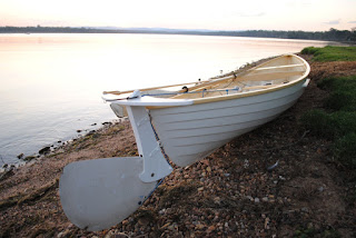
![]() |
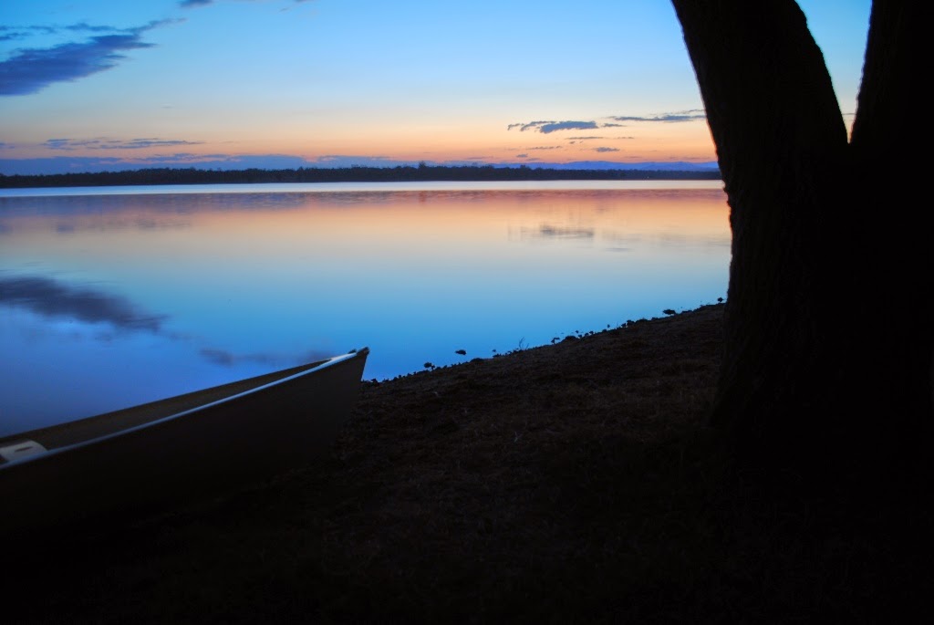
| Beach at Sunset |
The pair continued their conversation long into the night, covering many subjects, and occasionally went for a stroll along the low-water mark on the beach and headland. Moonlight made walking easy, but for most of the time they sat and talked, all the while watching the three boats as they sat at anchor, protected from the on-shore waves by the sandbar which made this place such a good anchorage...
Leaving the imaginary explorers to their imaginary adventures, I want to make a few observations. I used to be a purist and would go on dinghy cruising expeditions without an auxiliary outboard, and I also looked down on power-boats as a cruising option. With the benefit of (some!) maturity, I now realise that there is a place for engines in cruising, and that for a lot of trips the use of a proper powerboat is necessary in order to have the trip at all. Most of us have very limited time, and many destinations are out of reach in a sailing boat if there are only a few days available - but with a good powerboat, one can plan ahead with a reasonable expectation of maintaining a schedule. Of course, being weather-wise is absolutely essential, and being in a powerboat can demand as much seamanship as when sailing, rowing, or paddling.
I'm in the fortunate position of being able to enjoy all the above forms of boating. I go for day-sails in old racing dinghies with no auxiliary, I go dinghy-cruising in boats with free-standing masts, traditional rigs and a reliable outboard auxiliary, I row for exercise, I paddle a sea-kayak when I want to explore a headland or look at seabirds, and travel in a simple powerboat when there is a need to get somewhere and back fast. All of these give me enormous pleasure, and if sensible design choices are made, the boats can be cheaply constructed from readily available materials.
My strong advice is to select boats which are (regardless of category) smaller and more simple than you believe you need. The other really important thing is to avoid the temptation of altering the design. If a particular design is close to what you want, the urge to make a few alterations can be very hard to resist. But do not do it! Keep looking until you get the correct design, and if that is not possible, pay to have something designed especially for you.
While on the subject of selecting plans, don't get sucked into using unusually cheap plans - unless you have a very clear understanding of the qualifications and reputation of the designer. There are many which get advertised year after year, and obviously end up being bought by some unsuspecting customers. I've had to help a number of people who bought plans cheaply and ended up with trouble on their hands. I won't tell you the name of the designs, but be on your guard.
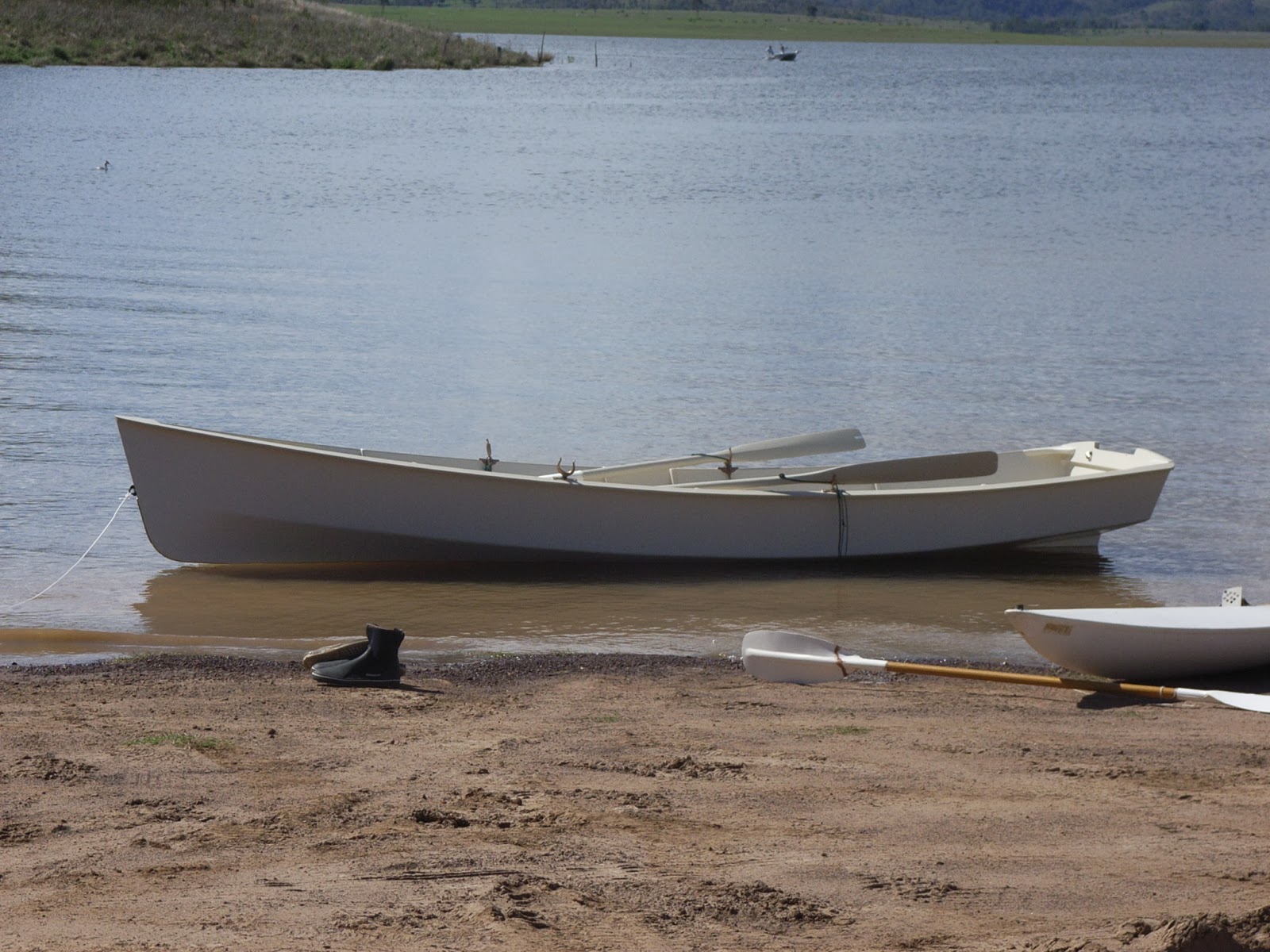
Having selected a design which satisfies your needs, build the boat with care, using the best materials you can afford. The amount of labour required to build a boat properly is such that saving a few dollars on cheap materials is a very false economy. My favourite boat is a plywood cruising dinghy, built at home in 1970. Today, at 43 years of age she is still going strong, and has paid for her first-cost many, many times over. Made of good-quality marine plywood, and excellent framing timber, her life is just about unlimited given sensible maintenance. However, if she had been built of exterior ply or some cheap, imported construction-grade ply, I very much doubt whether she would still be around. Well-built boats made from good-quality materials are still vastly cheaper than anything made commercially. In my experience, labour costs are always the most significant part of the cost of any boat. If you build a simple boat yourself, the labour costs you nothing but time, and you learn skills along the way for free.
![]() |
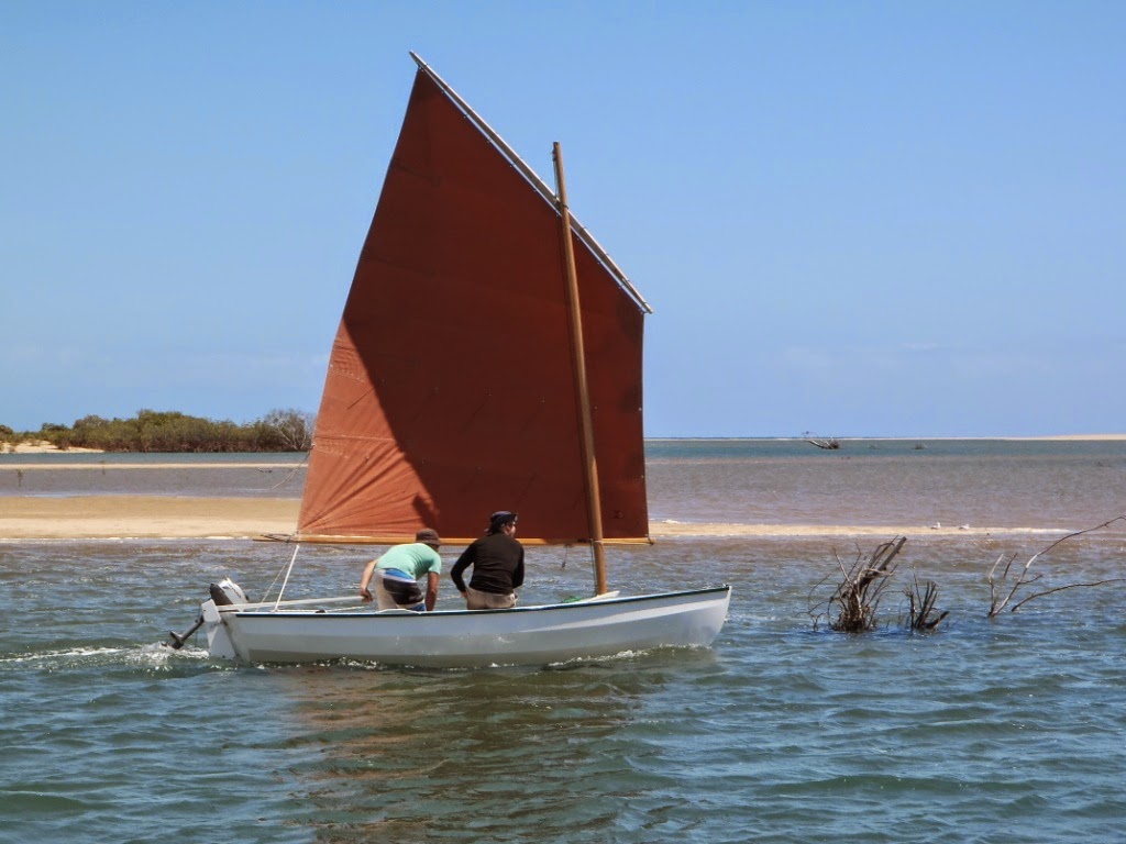
Homemade, simple, and inexpensive
(photo: Paul Hernes) |


.JPG)
.JPG)


+-+Copy.JPG)
+-+Copy.JPG)


.jpg)
.jpeg)


.jpg)

.JPG)


.jpg)